Download
1 / 38
390 likes | 414 Views
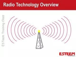
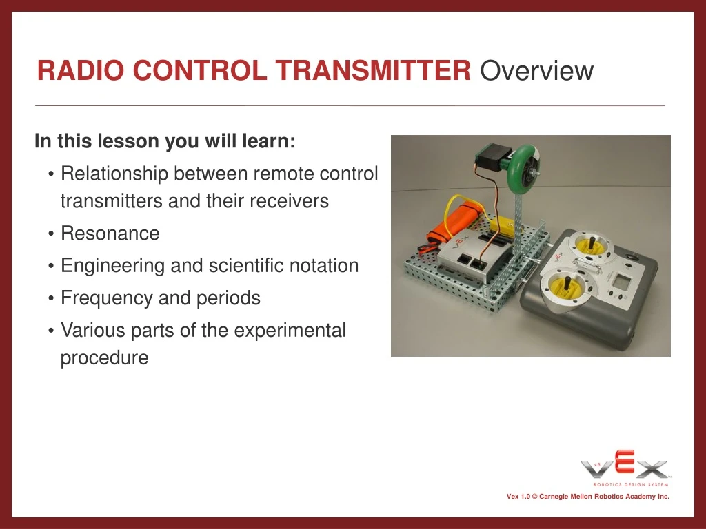
RADIO CONTROL TRANSMITTER Overview. In this lesson you will learn: Relationship between remote control transmitters and their receivers Resonance Engineering and scientific notation Frequency and periods Various parts of the experimental procedure. RADIO CONTROL TRANSMITTER Resonance.

E N D
RADIO CONTROL TRANSMITTEROverview • In this lesson you will learn: • Relationship between remote control transmitters and their receivers • Resonance • Engineering and scientific notation • Frequency and periods • Various parts of the experimental procedure
RADIO CONTROL TRANSMITTERResonance • The trumpet and the kettledrum • Consider a trumpet and a kettledrum, each tuned to the note of “E,” placed in the same room.
RADIO CONTROL TRANSMITTERResonance • The trumpet and the kettledrum • When the trumpet plays the “E” note, the sound wave leaves the trumpet and travels through the air.
RADIO CONTROL TRANSMITTERResonance • The trumpet and the kettledrum • The air molecules vibrate against the surface of the kettledrum, making the drum vibrate with an audible noise.
RADIO CONTROL TRANSMITTERResonance • What is resonance? • Resonance is the induction of vibrations on a physical object by a vibrating force having the same frequency. A dramatic example of resonance is demonstrated by the Tacoma Narrows Bridge disaster. Click “Background/Slide Shows/Tacoma Bridge: Example of Resonance” to see the video.
RADIO CONTROL TRANSMITTERGlossary • Glossary • Oscillate To swing back and forth with a steady, uninterrupted rhythm • Oscillator A device or mechanism for producing or controlling oscillations • Amplify To make larger; to increase • Amplifier To amplify an electric signal; to increase an electric signal
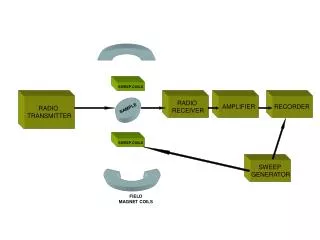
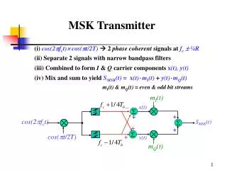
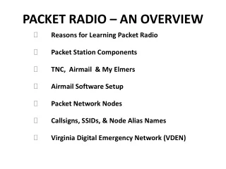
RADIO CONTROL TRANSMITTERSignals • How is a signal sent from the radio control transmitter? • A crystal is placed in the radio control transmitter • This is part of an oscillator circuit • The oscillator circuit sends electrons to vibrate the crystal • The crystal begins to vibrate at its resonant frequency • The oscillator circuit sends this signal to an amplifier • The amplified signal travels to an antenna • The electrical signal is changed to an airborne electromagnetic wave • Refer to “Multimedia / Vex Controller and Resonance”
RADIO CONTROL TRANSMITTERSignals • How does the the robotic system receive the signal from the radio control transmitter? • The Vex receiver uses an antenna to receive electromagnetic waves • Changes these waves to an electrical signals • The signal is amplified and sent ot the circuit containing the crystal • If the amplified signal is at the same frequency of the crystal in the receiver, then the crystal will generate a large sinusoidal signal • This activates another circuit which activates the motor • Refer to “Multimedia / Vex Controller and Resonance”
HORIZONTAL Antenna Test Transmitter / Receiver Range Horizontal Antenna Test Hypothesis Radio control transmission strength is a function of antenna height
Materials needed • Constructed robotic system (refer to “Resources / Signal Box Construction”) • Radio control transmitter • Yard stick • Tape measure • Lesson 1 datasheet (modified from “Resources / Lesson Datasheet”)
Step 1 • Place robotic system at stationary point • Turn on the Vex microcontroller and radio control transmitter • Make sure to have plenty of table or floor space for this experiment
Step 2 • Lay the radio control transmitter flat in front of the robotic system • Extend antenna 1” to gain minimal reception • Move as close as possible to the robotic system
Step 3 • Push the right joystick of the radio control transmitter forward to start the motor • Slowly slide the radio control transmitter away until the motor stops moving • Slide it back until a consistent connection is achieved
Step 3 continued • When you find and maintain a consistent signal, measure the distance from the radio control transmitter to the antenna of the reciever • Record the data in your Lesson 1 datasheet
Step 4 • Using the yard stick, extend the antenna to 4” • Follow the same procedure as in step 3 • Record the data in your Lesson 1 datasheet
Step 5 • Using the yard stick, extend the antenna to 8” • Follow the same procedure as in step 3 • Record the data in your Lesson 1 datasheet
Step 6 • Continue to extend the antenna in 4” increments and measure the distance from antenna tip to the receiver • Record the data at each increment • You will have 8 distances recorded in your Lesson 1 datasheet
Step 7 • Run another trial of this experiment and record the data in your Lesson 1 datasheet • Compare the graphs of both experiments • What do these results tell you about the relationship between transmission strength and antenna height?
VERTICAL Antenna Test Hypothesis Pointing the radio control transmitter away from (rather than directly towards) the robotic system will result in a stronger signal strength
Materials needed • Constructed robotic system (refer to “Resources / Signal Box Construction”) • Radio control transmitter • Yard stick • Tape measure • Lesson 2 datasheet (modified from “Resources / Lesson Datasheet”)
IMAGE OF CONTROLLER AND RADIO BEING TURNED ON Step 1 • Place robotic system at stationary point • Turn on the Vex microcontroller and radio control transmitter • Make sure to have plenty of table or floor space for this experiment
Step 2 • Place radio control transmitter upright in front of robotic system – the antenna should point toward the ceiling • Extend the antenna 1” to gain minimal reception
Step 3 • Push the right joystick of the radio control transmitter forward to start the motor • Slowly slide the radio control transmitter away until the motor stops moving • Slide it back until a consistent connection is achieved
Step 3 continued • When you find and maintain a consistent signal, measure the distance from the radio control transmitter to the antenna of the receiver • Record the data in your Lesson 2 datasheet
Step 4 • Using the yard stick, extend the antenna to 4” • Follow the same procedure as in step 3 • Record the data in your Lesson 2 datasheet
Step 5 • Using the yard stick, extend the antenna to 8” • Follow the same procedure as in step 3 • Record the data in your Lesson 2 datasheet
Step 6 • Continue to extend the antenna in 4” increments and measure the distance from antenna tip to the receiver • Record the data at each increment • You will have 8 distances recorded in your Lesson 2 datasheet
Step 7 • Run another trial of this experiment and record the data in your Lesson 2 datasheet • Compare the graphs of both experiments • Did pointing your radio control transmitter antenna towards (as in Lesson 1) or away from (as in Lesson 2) the robotic system result in a higher signal strength?
TEST with obstacles Hypothesis Different obstacles will affect the transmission of signals to the receiver
Materials needed • Constructed robotic system (refer to “Resources / Signal Box Construction”) • Radio control transmitter • Yard stick • Tape measure • Lesson 3 datasheet (modified from “Resources / Lesson Datasheet”) • Sheet of paper • Wood • Sheet metal
Step 1 • Place robotic system at stationary point • Turn on Vex microcontroller and radio control transmitter • Make sure to have plenty of table or floor space for this experiment
Step 2 • Hold radio control transmitter at waist height • Tilt antenna between 45 degrees and vertical • Extend antenna 1” to gain minimal reception
Step 3 • Place a piece of paper on top of the receiver • Make sure the antenna wire is wrapped around the receiver • Push the right joystick of the radio control transmitter forward to start the motor
Step 3 continued • Back away from the robotic system until the motor stops moving • Walk towards the system until a consistent connection is achieved • Measure the distance from the radio control transmitter to the receiver • Record the data in your Lesson 3 datasheet
Step 4 • Continue to extend the antenna in 4” increments and measure the distance from antenna tip to the receiver • Record the data at each increment • You will have 8 distances recorded in your Lesson 3 datasheet for the paper obstacle
Step 5 • Place a piece of wood on top of the receiver and the antenna • Repeat the same procedure as in steps 3 and 4
Step 6 • Place a piece of sheet metal on top of the receiver and antenna • Repeat the same procedure as in steps 3 and 4
Step 7 • Compare the graphs of all three experiments • Which material affected the signal strength of the radio control transmitter the most? • Which had the least effect?