Download
1 / 28
280 likes | 425 Views
Experience with Trigger Electronics for the CSC System of CMS.

E N D
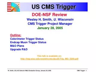
Experience with Trigger Electronics for the CSC System of CMS J. Hauser*, E. Boyd, R. Cousins, S. Haapanen, M. Mey, B. Mohr, J. Mumford, V. Valuev, J. Werner, Y. Zheng (UCLA), M. Matveev, P. Padley, J. Roberts, G. Veramendi (Rice U.), D. Acosta, A. Drozdetski, A. Korytov, A. Madorsky, B. Scurlock, H. Stoeck (U. Florida), B. Bylsma, S. Durkin, J. Gilmore, J. Gu, T.Y. Ling (Ohio State) *Presenter, hauser@physics.ucla.edu
CMS Detector Layout • CMS Endcap Muon System • Cathode Strip Chambers
. . . . . . . . . . . . . . cathode strips 3 - 16 mm avalanche wires Cathode plane wires cathode plane cathode strips avalanche 3.1 mm muon 9.5 mm Cathode Strip Chambers (CSC) • 6-layer chambers • Radial, trapezoidal cathode strips • Azimuthal anode wires • Induced charges on strips - precise f coordinate • Closely spaced wires - fast timing • Wires ganged in groups of 5 -16 for r coordinate
Front-end Electronics Requirements • Acquire data for muon hits • Cathode strips: precise f-coordinate determination by interpolation of induced strip charges. • DQ/Qtotal = 0.01 per CSC layer • Anode wire groups: precise timing for bunch crossing tagging and radial position determination. • 2 ns discriminator slewing • Generate primitives for Level-1 Trigger • Identify Local Charged Track (LCT) segments using cathode and anode signals Cathode charges Anode hits
Trig Motherboard Clock Control Board DDU,DCC Boards DAQ Motherboard C C B D M B T M B D M B T M B D M B T M B D M B T M B D M B T M B M P C T M B D M B T M B D M B T M B D M B T M B D M B Slow Control C O N T R O L L E R Muon Sector Receiver Lev-1 Trigger Readout Data Trigger-Timing-Control Peripheral Crate on iron disk 1 of 5 FED Crate in USC55 1 of 5 Cathode Front-end Board CFEB CFEB CFEB CFEB CFEB 1 of 2 LV Distribution Board 1 of 24 ALCT LVDB Anode LCT Board Anode Front-end Board CSC System Layout
CSC Trigger Elements • On-chamber: • AFEB (Anode Front-End Board) discriminates anode hits. • ALCT (Anode Local Charged Track) receives anode hits, forms anode muon stubs, and sends trigger information to TMB. • CFEB (Cathode Front-End Board) contains cathode amplifiers and trigger comparator ASICs that discriminate and find cluster positions to ½-strip accuracy. • Peripheral crate: • TMB (Trigger MotherBoard) receives anode stubs and cathode hits, forms cathode muon stubs, correlates in time with anode stubs, and sends matched muon stubs to MPC. One TMB per chamber. • MPC (Muon Port Card) receives muon stubs from 9 TMBs, send the 3 highest-quality stubs to the SRSP on optical links. • Counting house: • SRSP (Sector Receiver/Sector Processor) receives matched muon stubs from up to 4 stations, looks for tracks, and assigns muon track position and momentum.
Summer 2003 Beam Test Goals / • Multi-chamber system test using preproduction versions of off-chamber electronics. • Re-verify triggering with high spatial resolution and bunch ID efficiency. • Check the high-rate system capability.
May-Sept. 2003 CSC Beam Test Setup at CERN X5A TTC crate Trigger primitives DAQ Data PC FED crate 1 DDU Track Finder Crate Peripheral Crate 2 DMB, 2 TMB 1 CCB, 1 MPC TRIDAS • 2 CSC’s, all on-chamber boards • Up to 80K events read out in 2.6s spill beam S1 S3 S2 CSC 2 CSC 1
On-chamber CSC Trigger Electronics • Comparator ASICs • Compare pulse heights from adjacent strips to find cluster to ½-strip • 15000 16-channel ASICS on CFEB boards (OSU) • Production complete • ALCT Boards • Finds tracks among anode hits, stores data for readout • XCV600 and XCV1000s used for main FPGA • 468+spares boards of 3 types (288-, 384-, 672-channel) • Production complete (making more spares)
Peripheral Crate:Trigger Motherboard • Generates Cathode LCT and matches ALCT with CLCT • 9U x 400 mm form factor • Uses XC2V4000 for main FPGA • 32 pre-production boards have been built (CMS uses 468) Front-panel CFEB Input connectors ALCT input connectors
12 Used in CMS System Track Finder Crate:SP2002 (Main Board) Receiver: • Optical Transceivers • 16 x 1.6 Gbit/s Links VME/CCB FPGA TLK2501 Transceiver Data conversion: Phi Global LUT To/from custom GTLP back-plane Eta Global LUT Phi Local LUT Front FPGA
Trigger Primitive Algorithms: Anodes • 6 layers * up to 112 wire groups per layer (672 channels) • Hits delayed in 2ns steps to optimum phase for timing, then recorded every 25 ns bunch crossing (BX). • In each anode pattern, pre-trigger when e.g. 2 layers receive hits. • Confirm pre-trigger with e.g. 4 or more layers with hits within a pattern. • ALCT board outputs up to 2 ALCTs per chamber/BX. Choose those having maximum number of layers. • Logic is fully programmable: plenty of adjustments are allowed. xxx__ layer 0 _xx__ layer 1 __x__ layer 2 __xx_ layer 3 __xxx layer 4 __xxx layer 5 Anode Collision Muon Pattern
1.2 ms 23 ms SPS orbit period 2003 Synchronous Beam Structure 48 bunches 25 ns bunch spacing bunch width 3-5 ns Structure repeats during 2.6 s spill length
BX efficiency vs. ALCT delay setting 0-31 ns Structured Beam Bunch Structure and ALCT Delay Tuning • Expect muons in 48 out of 924 bx verified by CLCT BXN from data Chamber 1 Chamber 2
Chamber 1 • Chamber 2 BX Distributions WithOptimal Anode Delays • Note logarithmic scale • Cathodes: • Data mostly in 3 BX (no fine time-adjustment possible) • Anodes: • Data 98.7%in 1 BX
TMB Patterns __x_ layer 0 __x_ layer 1 _xx_ layer 2 _x__ layer 3 xx__ layer 4 x___ layer 5 pattern 7 x___ x___ xx__ _x__ _xx_ __x_ pattern 1 _x__ _x__ _x__ _x__ __x_ __x_ pattern 2 x___ x___ xx__ _x__ _x__ _x__ pattern 3 _x__ _x__ _x__ _x__ _x__ _x__ pattern 4 __x_ __x_ _xx_ _x__ _x__ _x__ pattern 5 _x__ _x__ _x__ _x__ x___ x___ pattern 6 Trigger Primitive Algorithms:Cathodes • 6 layers * up to 80 wire groups per layer (480 channels) • Form “di-strips” by OR’ing 4 adjacent ½-strip bits. • In each cathode pattern, pre-trigger when 2 layers are hit, confirm pre-trigger when 4 layers are hit. • Simultaneous ½-strip patterns for high-PT muons, di-strip patterns for low-PT muons: • CLCT board outputs up to 2 CLCTs per chamber/BX. Choose those having: • Maximum number of layers. • ½-strip patterns preferred over di-strip patterns. • Straightest pattern. • Logic is fully programmable: lots of adjustments are allowed.
Comparator ½-strip ID • Particles tracked using precision charge readout on cathodes • Position difference between center of ½-strip and the fitted track:
Cathode Comparator Behavior • Source of imperfect ½-strip resolution due to imperfect comparators • Resolution ~5 ADC counts (2.9 fC) • Offset ~8 ADC counts (4.6 fC)
Correct or +-1 half-strip ID Correct strip ID Perfect ½-strip ID Comparators vs. Cluster Charge • At low cluster charge, e drops due to too little charge for comparison • At highest cluster charge, e drops due to slow saturation of amplifiers
Zoom CLCT Position Correlations • Relative position of CLCTs from Chamber 2 vs. Chamber 1 • N.B. Chamber 1 is vertically higher than Chamber 2 (thus the offset in position).
Angle Scan: Cathode Trigger (CLCT) Patterns • Simultaneous searches for di-strip patterns • (low-Pt) • and half-strip patterns • (high-Pt) • Simulate low-Pt by tilting the chamber (phi)
f=0o • HQ • straight • 1/2-strip f=5o • HQ • bent • 1/2-strip • HQ • bent • 2-strip f=20o 1/2-strip patterns 2-strip patterns Quality = Layers-3
Quality (layers) • Pattern CLCT Quality, Pattern vs. Chamber Tilt • Phi_b (tilt)
Chamber #1 CLCT 2,000 1,500 CLCT Rate (KHz) 1,000 data consistent with dead-time = 225 ns 500 0 0 500 1,000 1,500 2,000 2,500 3,000 Beam Intensity (KHz) Expected LCT rate at LHC is 97 KHz/chamber (ME1/1) (CMS note 2002-007) Trigger Primitive Rate Tests Max. LHC Max. LHC
Trigger Primitive Algorithms:Matching and other Notes • TMB anode-cathode matching is done primarily by timing. • If 2 ALCT and 1 CLCT or vice versa are found, two matched stubs are reported by copying the single stub view. • If 2 ALCT and 2 CLCT are found, they are matched by the number of layers. • Trigger hits and stub information are all read out to the DAQ system for 16 BX, starting 2 to 5 BX before the first hit.
Absolute ALCT*CLCT Efficiency abs(wg3-wg8) abs(strip3-strip8) Given an ALCT*CLCT matched stub in chamber 1, the efficiency for a matched stub in Chamber 2 can be found. Using a 5 strip and 3 wire-group tolerance: • e=97.9% in one BX • e=98.9% in two BX (correct BX or one after) • e=99.1% in three BX (correct BX 1) as determined from logged Track-Finder data abs(strip3-strip8) abs(wg3-wg8)
Conclusions • This was the first time the CMS endcap muon group demonstrated a complete electronics chain from chamber to muon tracks using pre-production electronics. • The CSC trigger (and DAQ) system performed extremely well at the 2003 test beam. • A few hardware problems were found (e.g. optical link clocking) and have since been addressed. • Further “system integration” tests are underway at 2004 test beams at CERN.