Download
1 / 27
270 likes | 277 Views
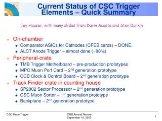
CSC Trigger. Darin Acosta University of Florida Also representing UCLA and Rice University. CSC Muon Trigger Scheme. EMU. TriDAS. On-Chamber Trigger Primitives. Muon Port Card (Rice). 3-D Track-Finding and Measurement. Trigger Motherboard (UCLA). Strip FE cards.

E N D
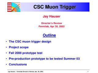
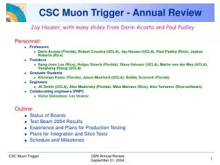
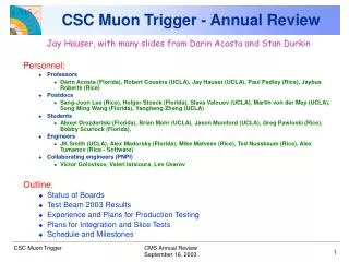
CSC Trigger Darin Acosta University of Florida Also representing UCLA and Rice University
CSC Muon Trigger Scheme EMU TriDAS On-Chamber Trigger Primitives Muon Port Card(Rice) 3-D Track-Finding and Measurement Trigger Motherboard(UCLA) Strip FE cards Sector Receiver/ Processor(U. Florida) LCT OPTICAL FE SP SR/SP MPC LCT TMB 3 / port card FE 2 / chamber 3 / sector Wire LCT card TF crate(1) Wire FE cards Peripheral crates (60) RAT CSC Muon Sorter(Rice) RPC-ALCT Transition card RPC DT 4 4 4 Global L1 Global Trigger 4
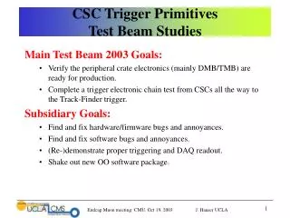
CSC Trigger Primitives Local Charged Track (LCT) logicidentifies track stubs in CSCs Cathode strips • Cathode strips: precise f-coordinate (bending direction) determination in each layer by interpolation of induced strip charges. • Anode wire groups: precise timingfor bunch crossing tagging and radial position determination.
Muon Track-Finding • Link trigger primitives into 3D tracks • Measure pT, , and in non-uniform fringe field • Send highest qualitycandidates to Global Trigger • Partitioned into 60° sectors that align with DT chambers
Trigger Motherboard Production Status • TMB board layout was re-done: • Solves noise problems (tested) • Prototypes (2) were recently produced • Preproduction of ~30 boards started • All parts are in hand, except for some machined panels (not a problem) • Requires re-design of peripheral crate backplane (done, in test) • Mezzanine (XC2V4000) cards: • 220 cards in hand • Only about 5 have problems • Another 120 being assembled this month EMU project, UCLA
Muon Port Card TriDAS, Rice Univ. VME Interface (glue logic) To Track-Finder GTLP Receivers Sorting logic:18 3 LCTs TLK2501 serializers Optomodules Mezzanine card
Muon Port Card Production Status • 75 production boards have been assembled and checked at Rice (60 used in system) • 70 boards are equipped with mezzanine FPGA • 47 boards passed a burn-in test at OSU and re-tested at Rice Onefailed the chain-test Will bake the other boards soon
Chain Test of the MPC with TMB All prototype, preproduction, and production boards have been required to pass a set of thorough chain tests. • Load random patterns into 9 TMBs • Send them out simultaneously from all TMBs at 80Mhz • Check data from FIFO_B at MPC (results of sorting) • Check feedback “winner” bits from TMBs • Check data from input FIFO at SP after optical transmission • Measure “safe window” of data latching from nine TMBs
CSC Track-Finder Crate Single crate system, in production now Clock & Control Board Sector Processor SR SR SR SR SR SR SR SR SR SR SR SR CCB MS / / / / / / / / / / / / SP SP SP SP SP SP SP SP SP SP SP SP CAEN VME Controller From MPC (chamber 4) Muon Sorter From MPC (chamber 3) From MPC (chamber 2) From MPC (chamber 1B) From MPC (chamber 1A) To DAQ Interfaces: 180 optical links from 60 EMU peripheral crates (3 fibers/crate from MPC) 72 SCSI cables to/from DTTF crates
Sector Processor Production Board Florida Phi Global LUT Eta Global LUT Phi Local LUT Front FPGA TLK2501 Transceiver • Optical Transceivers • 15 x 1.6 Gbit/s Links TF logic mezz card
SP Production and Test Status • The previous Sector Processor prototype, SP02, has been fully validated and used as a trigger for CSC beam tests in 2003-2004 • 3 boards exist, all in use: one at CERN (for Slice Test) and rest at Florida and Rice (for MPC and SP production tests) • The production version, SP04, is fully compatible with SP02 • Significant delay and problems occurred with initial vendor • ~4 month total delay due to poor assembly by initial vendor • Same vendor as for SP02 prototype! • After significant re-working by other companies, first two production boards pass single board validation checks • Second vendor was selected to complete SP production • First 2 assembled boards (3rd and 4th in production) have been received and are under test • One board passes all single board tests including optical loop-back and full SP functionality check (3000 iterations of 255 BX of random data input) • Will perform chain test with MPC and MS before launching rest of production (17 more modules)
SP/MS Mezzanine Card Status • Contains Track-Finding algorithm • Same mezzanine card is used for Muon Sorter • The previous (2002) prototype was fully validated • Production version of mezzanine card fully compatible with prototype • Production is nearly complete • Despite some initial problems with connector assembly, 14 new mezzanine cards have been fully validated (+5 old) • 2 others show some discrepancies and are under investigation
Muon Sorter Rice Univ. VME/JTAG INTERFACE MEZZANINE CARD LVDS DRIVERS AND SCSI-3 CONNECTORS GTLP BACKPLANE INTERFACE From SP’s Sorting logic: 36 4 tracks, output to GMT, 1 needed
MS Tester Board (SP emulator) • We would like to test the MS with a full crate of SP’s • Since all there is in the final system is one crate of SPs, it is not practical to wait for the SPs • Instead, we built a simple board for injecting trigger patterns • We can fill the crate with these and perform chain-test with the MS
TF Chain Test Results • Full TF crate tests with SP emulator boards shows some problems with grounding • Solution found and tested. • Muon Sorter and TF backplane are under redesign New ground planes and new signal routing will be implemented on TF backplane (Florida)
Muon Sorter to Global Muon Trigger Test • Muon Sorter – Global Muon Trigger Test was successfully conducted in January • There was a VME access error when TTC used to clock system, but cannot reproduce at Rice
Schedule • SP • Assuming no unexpected problems, foresee final 16-board production to start in July • Board testing should be complete by end of September • MS • Re-design and fabrication complete by end of September • TF backplane • Backplane redesigned. Fabrication complete end of July • Ready for fully-loaded TF crate tests by October • Testing with Muon Sorter and TF backplane at Rice University in U.S. • 2 months, with old and new versions of MS and BP • Fully validated TF crate by end of 2005
Plans for Commissioning at Bat. 904 • Integration tests with CSC trigger production electronics (i.e. full-crate tests of Track-Finder electronics and peripheral crate electronics) are taking place in the U.S. • Tests will be repeated at Bat.904 when boards are shipped to CERN later this year • Expect to make use of Bat.904 also for integration tests with other subsystems • In particular, further CSC TF DT TF integration tests to work on synchronization procedures, combined Track-Finding, and software integration • Currently we have one complete CSC TF setup @ CERN (SP2002 prototype), currently occupied with CSC Slice Tests at SX5
ME4 DT-11 DT-10 ME3 ME2 ME1 CSC Slice Tests & Cosmic Challenge • Incremental steps to a complete slice test during the CMS Cosmic Challenge • Work began in earnest at SX5 inmid-April • Currently connected 6 chambers in ME+2 and ME+3, forming a 20° slice on YE+2 that is part of the trigger sector planned for the Cosmic Challenge • CSC Track-Finder will provide a cosmic muon trigger based on a coincidence of LCTs in two or more disks
Track Finder Crate @ SX5 • Currently set-up as we operated during the 2004 beam tests • Except no scintillator trigger available! • Developing procedures and software to test the system and to time-in and synchronize the CSC trigger with no other external inputs SP
CSC Trigger “Boot-Strap” Procedures Detailed procedures being developed on how to time-in and bring to operation the CSC trigger at CMS using injected data and no other external triggers: • Board validation checks • Test distribution of L1Request from SP to TTC tree • MPC to SP optical link synchronization procedure • MPC to SP PRBS test • MPC to SP Spy FIFO Test • Synchronization of SP Pipeline FIFO (for SP DAQ) • Synchronization of received TMB LCTs (chamber data!) using single chamber trigger • Two-station coincidence cosmic trigger implemented
Run-control and Quality Control Software • As part of the testbeam and Slicetest programs, online control software using XDAQ and HAL has been in development • During 2004 testbeams, a CMS prototype Run Control program was used to configure the Peripheral Crates, Track-Finder crate, TTC and FED crates using XDAQ • For production QC, HAL-based software is used to test all board functionality and to perform trigger chain tests • e.g. many iterations of random input data are injected, and the board output is compared with an exact emulator • Caught some grounding issues with full TF crate test • For Data Quality Monitoring, a sophisticated framework based on the CDF DQM is used by the EMU group • Was used to monitor trigger boards in the peripheral crates during testbeams (continuing to Slicetest)
Simulation Software (for PTDR) • Fairly accurate simulation of the CSC trigger chain is in ORCA • For the SP, a direct translation of the Verilog firmware is implemented, which yields exact agreement with testbeam data • Other boards have approximate functional simulation, but not necessarily exactly bit-for-bit simulation • Some details need updating to latest production board designs and firmware • Further optimization and improvements could still be done: • Muon PT and charge assignment • Tuning of LCT patterns for best efficiency vs. background rejection • BX assignment
Muon Trigger Geometry Initial coverage of RPC is staged to <1.6 Initial coverage of CSC 1st station is staged to <2.1
. . . . . . . . . . . . . . cathode strips 3 - 16 mm avalanche wires Cathode plane wires cathode plane cathode strips avalanche 3.1 mm muon 9.5 mm Cathode Strip Chambers • 6-layer chambers • Radial, trapezoidal cathode strips • Azimuthal anode wires • Induced charges on strips - precise f coordinate • Closely spaced wires - fast timing • Wires ganged in groups of 5 -16 for r coordinate