Download
1 / 1
10 likes | 136 Views
a). c). b). a). b). c). d). e). Rigorous Analysis of Finline Tapers for High Performance Millimetre and Submillimetre Detectors. Chris North, Ghassan Yassin and Paul Grimes - Astrophysics, Oxford University. Overview

E N D
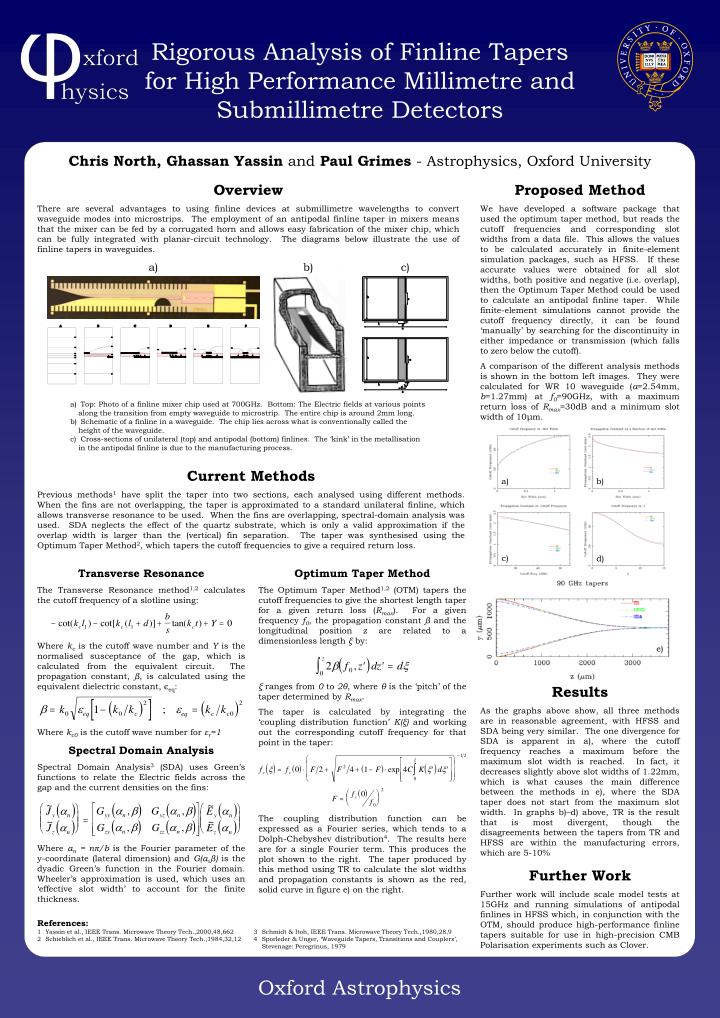
a) c) b) a) b) c) d) e) Rigorous Analysis of Finline Tapers for High Performance Millimetre and Submillimetre Detectors Chris North, Ghassan Yassin and Paul Grimes - Astrophysics, Oxford University Overview There are several advantages to using finline devices at submillimetre wavelengths to convert waveguide modes into microstrips. The employment of an antipodal finline taper in mixers means that the mixer can be fed by a corrugated horn and allows easy fabrication of the mixer chip, which can be fully integrated with planar-circuit technology. The diagrams below illustrate the use of finline tapers in waveguides. Proposed Method We have developed a software package that used the optimum taper method, but reads the cutoff frequencies and corresponding slot widths from a data file. This allows the values to be calculated accurately in finite-element simulation packages, such as HFSS. If these accurate values were obtained for all slot widths, both positive and negative (i.e. overlap), then the Optimum Taper Method could be used to calculate an antipodal finline taper. While finite-element simulations cannot provide the cutoff frequency directly, it can be found ‘manually’ by searching for the discontinuity in either impedance or transmission (which falls to zero below the cutoff). A comparison of the different analysis methods is shown in the bottom left images. They were calculated for WR 10 waveguide (a=2.54mm, b=1.27mm) at f0=90GHz, with a maximum return loss of Rmax=30dB and a minimum slot width of 10μm. • Top: Photo of a finline mixer chip used at 700GHz. Bottom: The Electric fields at various points along the transition from empty waveguide to microstrip. The entire chip is around 2mm long. • Schematic of a finline in a waveguide. The chip lies across what is conventionally called the height of the waveguide. • Cross-sections of unilateral (top) and antipodal (bottom) finlines. The ‘kink’ in the metallisation in the antipodal finline is due to the manufacturing process. Current Methods Previous methods1 have split the taper into two sections, each analysed using different methods. When the fins are not overlapping, the taper is approximated to a standard unilateral finline, which allows transverse resonance to be used. When the fins are overlapping, spectral-domain analysis was used. SDA neglects the effect of the quartz substrate, which is only a valid approximation if the overlap width is larger than the (vertical) fin separation. The taper was synthesised using the Optimum Taper Method2, which tapers the cutoff frequencies to give a required return loss. Transverse Resonance The Transverse Resonance method1,2 calculates the cutoff frequency of a slotline using: Where kc is the cutoff wave number and Y is the normalised susceptance of the gap, which is calculated from the equivalent circuit. The propagation constant, β, is calculated using the equivalent dielectric constant, єeq: Where kc0 is the cutoff wave number for εr=1 Spectral Domain Analysis Spectral Domain Analysis3 (SDA) uses Green’s functions to relate the Electric fields across the gap and the current densities on the fins: Where αn = nπ/b is the Fourier parameter of the y-coordinate (lateral dimension) and G(α,β) is the dyadic Green’s function in the Fourier domain. Wheeler’s approximation is used, which uses an ‘effective slot width’ to account for the finite thickness. Optimum Taper Method The Optimum Taper Method1,2 (OTM) tapers the cutoff frequencies to give the shortest length taper for a given return loss (Rmax). For a given frequency f0, the propagation constant β and the longitudinal position z are related to a dimensionless length ξ by: ξ ranges from 0 to 2θ, where θ is the ‘pitch’ of the taper determined by Rmax. The taper is calculated by integrating the ‘coupling distribution function’ K(ξ) and working out the corresponding cutoff frequency for that point in the taper: The coupling distribution function can be expressed as a Fourier series, which tends to a Dolph-Chebyshev distribution4. The results here are for a single Fourier term. This produces the plot shown to the right. The taper produced by this method using TR to calculate the slot widths and propagation constants is shown as the red, solid curve in figure e) on the right. Results As the graphs above show, all three methods are in reasonable agreement, with HFSS and SDA being very similar. The one divergence for SDA is apparent in a), where the cutoff frequency reaches a maximum before the maximum slot width is reached. In fact, it decreases slightly above slot widths of 1.22mm, which is what causes the main difference between the methods in e), where the SDA taper does not start from the maximum slot width. In graphs b)–d) above, TR is the result that is most divergent, though the disagreements between the tapers from TR and HFSS are within the manufacturing errors, which are 5-10% Further Work Further work will include scale model tests at 15GHz and running simulations of antipodal finlines in HFSS which, in conjunction with the OTM, should produce high-performance finline tapers suitable for use in high-precision CMB Polarisation experiments such as Clover. References: 1 Yassin et al., IEEE Trans. Microwave Theory Tech.,2000,48,662 2 Schieblich et al., IEEE Trans. Microwave Theory Tech.,1984,32,12 3 Schmidt & Itoh, IEEE Trans. Microwave Theory Tech.,1980,28,9 4 Sporleder & Unger, ‘Waveguide Tapers, Transitions and Couplers’, Stevenage: Peregrinus, 1979