Download
1 / 29
290 likes | 449 Views
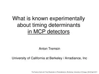
What is known experimentally about timing determinants in MCP detectors. Anton Tremsin University of California at Berkeley / Arradiance, Inc. 1. Event time measured by the signal from the MCP output electrode.

E N D
What is known experimentally about timing determinants in MCP detectors Anton Tremsin University of California at Berkeley / Arradiance, Inc
1. Event time measured by the signal from the MCP output electrode. Need to synchronize that signal with the spatial data coming on a separate electronics channel. At high rates may be a challenge. 2. Event time measured by the signals from the anode.Both spatial and temporal channels are from the same signal, no need to synchronize. Event timing signal pickup
Event timing variation across 18 mm tube Event time measured by the signals from the anode: TTS is increased by the presence of the energy distribution in the MCP output electron signal.
Event timing variation across 18 mm tube There is a variation of event time across the field of view in case of the signal pickup from the MCPout electrode. Map of the variation in event arrival time, showing variation in amplifierdelay for the RD20 32 channel chip.18mm sealed tube cross strip detector. Variation in event arrival time in a horizontal slice of the image above. Across the middlethe variation is less than 500 ps. O.H.W. Siegmund, et al., AMOS 2010
Event timing variation across 18 mm tube Event timing is determined by the signal to noise ratio. Time stamp jitter as a function of MCP gain. See plot on right for details. Time jitter for the event time stamp as a function of MCP gain. Showing better performance at higher gain. O.H.W. Siegmund, et al., AMOS 2010
Single photon/electron counting: detector hardware Active area, 25 mm A. S. Tremsin, et al., Nucl. Instr. Meth. A 580 (2007) 853. A. S. Tremsin, et al., IEEE TNS 54 (2007) 706.
2D Imaging +time for eachdetected photon Scattered photons Synchrotron generated photon pulses ~ 70 ps wide, 2 ns apart Thin film samples Experimental setup A. S. Tremsin, et al., Nucl. Instr. Meth. A 580 (2007) 853. A. S. Tremsin, et al., IEEE TNS 54 (2007) 706.
Timing accuracy 55 ps RMS Timing resolution: single photoelectron Elastically scattered photons A. S. Tremsin, et al., Nucl. Instr. Meth. A 580 (2007) 853. A. S. Tremsin, et al., IEEE TNS 54 (2007) 706.
Inelastic X-ray scattering Both elastic and inelastic scattering are present Only elastic scattering
Timing resolution vs. MCP gain Photon peak measured by the detector:Gain 7e5 FWHM=283 psGain 2e6 FWHM=200 psGain 3.5e6 FWHM=165 ps (all data taken at this gain)
Synchrotron bunch diffusion measured with MCP Bunch population ~76 min later Bunch population after injection Diffusion of electrons between the adjacent bunches was optimized with our detection system W. E. Byrne, et al., Proceedings EPAC’06, Edinburgh, June 2006
Event timing correction: XY→Tcorrected XY map of events on the anode: correlate event time with the XY position. Correct for transit time at the anode. In our system the jitter was limited by something else, not by transit of electron signal at the anode.
MCP output pulse with a 50W anode 25 um pores 10 um pores Peter Wurz and Lukas Gubler, Rev. Sci. Instrum. 67 (5), 1996
Signal pick up from the MCP or from the anode 40 mm active diameter MCPs mounted in a Chevron configuration. 5 mm pore MCP, L/D=60:1, 12° bias MgO coating for optimum electron detection. • Measured by taking the pickup signal from the back of MCP plate which is preamplified and processed by the TAC B&H SPC-130. • Average of the time sum in the delay line one direction as measured on the delay line signals by the eight-channel TDC (Roentdek TDC8HP). Arno Vredenborg, Wim G. Roeterdink, and Maurice H. M. Janssen, Review of Scientific Instruments 79, 063108 2008
Detector walks: what can be learned from XS detector Each strip has preamplifiers and 50 MHz ADC. Digital waveform is processed. Same effects are present as in LAPPD detector, but at longer time scales. A. S. Tremsin, et al., IEEE Trans. Nucl. Sci. 56 (2009) 1148
Event timing calculation through CFD A. S. Tremsin, et al., IEEE Trans. Nucl. Sci. 56 (2009) 1148
Self triggered timing resolution Pulse generator produced pulses amplified by the RD20 readout board. Digital peak detection A. S. Tremsin, et al., IEEE Trans. Nucl. Sci. 56 (2009) 1148
Large panel detector questions • The smallest pore size for 8” MCPs (20 um or 10 um) • Gap between the MCPs – poor Pulse Height Distribution - is one MCP configuration possible? • Distance to photocathode to be minimized (J. Va’vra results) • Charge footprint to be spread over ~4 mm – timing of the pulse is broadened • Walk effects – both temporal and spatial (with event gain) • Gain required for detector operation (signal to noise defined by the front end electronics and anode)