Download
1 / 79
790 likes | 892 Views
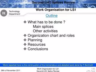
High current splices. Summary of this talk. Quality assurance for the present interconnect work: Qualification work, modifications of machines Control of parameters Interconnect follow up (Christian Scheuerlein) Quality assurance for the series production Quality plan

E N D
Summary of this talk • Quality assurance for the present interconnect work: • Qualification work, modifications of machines • Control of parameters • Interconnect follow up (Christian Scheuerlein) • Quality assurance for the series production • Quality plan • Measurement of electrical resistance during production • Mechanical QA testing during production • Mechanical efforts on the 13 KA junctions • Nominal cases • Reduced overlap • Summary of and electrical test on 13 KA joints to build high resistance splices • Possible clamping
In other talks • Data mining: Nuria Catalan Lasheras • Calorimetric and voltage measurements: Nuria Catalan Lasheras
Quality control approach The Quality Assurance (QA) strategy is based on four concepts: • Prior qualification of the processes, the equipment and the operators on samples; • On-line monitoring and recording of critical parameters of all junctions; • Strict application of the qualified procedures and full traceability; • Production samples that can be tested off-line using destructive methods. • From January 2007 till June 2007 72 persons were affected to QC tasks. 110 were performing the assembly work
Controlling the quality I: the brazing • Before interconnecting: • Interconnection qualification performed by ICIT (CERN) team • Intervention of the CERN team for repair if necessary • IEG inspection • During the bus bar soldering • Control of the pressure and temperature performed by the machine: if they do not fit inside the acceptable window the machine stops and/or indicate the a defective joint on the screen at the end of the cycle • The pressure is measured via the hydraulic circuit • The temperature via a thermo-couple embedded in the joint • After the soldering • Visual control by the operator according to CERN agreed procedure • Geometrical defects: misalignment and lack of continuity between the pieces • Presence of soldering material in the junction between pieces • The operator fills in the traveler • The recorded data are transferred to the company office and then in the CERN quality system (problem of quality of data) • The quality controller of the team checks the work and the traveler. If he detects a problem • Open a NCR • In case of doubt contact the CERN reference person for verification
Controlling the quality II: after the soldering • Cleaning of the bus bar • Insulation of MB • US welding of the spool bus bars • Completion of the insulation with control performed by the operator. • Electrical tests on half cells • Checking on the insulation before the welding of the M lines: re-performed by the welder team leader
Controlling the quality III: the CERN role I • Verification of application of the procedures: • Audits performed by CERN technician sampling the teams • Tests on the assembly: electrical tests • PAQ tests (54): on pieces of the machine of 54m (half cell), 3 interconnects: 500 V, 30 sec, more in case of doubt (humidity …) • Connection of the half cells to form 5 sub-sectors: DS R, 11R-25R 25R-25L 25L-11L DSL, welding of the M lines sleeves in the PAQ tested interconnections • MPAQ tests(5): 500 V 120 sec. more in case of doubt • Closing of the interconnects and leak tests • TP4-A 600 V 6 bar • TP4-E 1.9 KV 1 bar
Controlling the quality III: the CERN role II • Tests of the machines: we used 8 machines. Every week one machine was selected to produce 2 samples for • Electrical resistivity tests: 70 tests were performed • Mechanical tests: 56 tests were performed • Each machine before being put in in service was qualified on samples to be mechanically and electrical tested • US check of the joint quality: 230 (about 1380 joints) interconnects were sampled mainly in sector 6-7 and 1-2. 1 joint was found to be doubtful and re-soldered.
Data on qbqi.24 r3 • Dates • Brazing performed the 07/12/2006 Thursday. Team Cescutti-Yanez • Checked by the IEG QC the 11/12/2006 Monday. L. Bouilly • Recorded by the team leader on the 11/12/2006. M. Souayah • Isolation main bus bar. OvivierStefanidi 11/12/2006 • Team performing the work • Cescutti: leader contract started 23/01/2006 end 08/02/2007 • Yanez: help contract started 31/08/2005 end 15/05/2007
Audits Audits were the most difficult tool to put in place: • In order to get the confidence of the workers • In order to pass effectively the message to the company on the points to be improved They started in October 2006, in January they started to become very effective because of the relationship of technical trust that the workers built with the auditors that became their technical references
Date recorded i.e. QQBI.23R3 Unfortunately only 30% of the LHC production data are exploitable: the choice of flash memory card to store the data has proven not to be strong enough to stand the environment near the HF generator of the inductive system
Acceptability range for resistance • According to document LHC-QBBID-ES-0001 the resistance at 4.2K shall be less then 0.6 nΩ • The following guidelines for the evaluation of the tunnel samples have been implemented: From 0 nΩ to 0.11 nΩ: too low not acceptable sample From 0.12 nΩ to 0.2 nΩ: ok From 0.21 nΩ to 0.55 nΩ: strict machine follow up From 0.55 nΩ to 0.6 nΩ: stop machine Above 0.6 nΩ out of tolerance stop machine Attention: a geometrically well done joint with no flux and no extra soldering in addition to the one present on the SC cables after stripping present a resistance of 0.3-0.35 nΩ
Joint resistance measurement on samples Copper cover twisted: joint non conform it was decided to ahead to see the effect on the joint resistance
Electrical tests on machine BR 2 Period of use in sector 3-4
Electrical tests on machine BR4 Period of use in sector 3-4
Electrical test on machine BR7 Period of use in sector 3-4
Special tests During the interconnection in sector 3-4 a special tests was performed • 4 long dipole bus bar elements were prepared (80 cm on each side) • The 4 elements were interconnected by IEG operator using production machine in the tunnel on the 28/11/06 (sector 3-4 !!!) • N. 1: with standard interconnect • N. 2: forgetting the soldering material between the 2 cables • The 2 elements were measured in the Fresca facility: • N.1 0.38 nΩ • N.2 0.28 nΩ
Mechanical test procedure and acceptance limits • At room temperature • Fatigue life cycle: 5000 cycles from 20 N to 240 N • Tensile test: minimum force for joint breakage 900 N • At 4.2 K • Fatigue life cycle: 5000 cycles from 40 N to 510 N • Tensile test: minimum force for joint breakage 1000 N • Total number of tests performed: 34 R.T., 46 4.2 K
Production samples The check was performed by the execution, by the same operators using that specific machine, of two production samples. After a visual inspection, the samples were tested electrically at the CERN cryolab and thereafter mechanically at the EIG (Ecoled’Ingénieurs de Genève). Important: no one of the joints tested was broken during the tests. A test was stopped because 1) An upper test limit due to the test set up was reached ( typically 2 KN for the 4.2 K and 5 KN for the R.T. tests) 2) A discontinuity on the loading curve was observed (see case I and case II) and that value was declared the limit of the joint
Tests of main machines used in 3-4 • Machine BR4 tested conform on the • 20/09/06 R.T. fatigue 4.2K tensile (>5000 N) • 31/10/06 4.2 K fatigue and tensile test (>4800 N) • 23/01/07 R.T. fatigue and tensile test (>1900 N) • 06/02/07 4.2K fatigue and tensile test (>5000 N) • Machine BR7 tested conform on the • 11/10/06 R.T. and 4.2 K. fatigue and tensile test (>1900 N and >4000 N) • 23/01/07 R.T. fatigue and tensile test (>1900 N) • 06/02/07 4.2 K fatigue and tensile test (> 4000 N)
UltrasoundChecks on Busbars M1,M2,M3 An ultrasound diagnostic system probing along a horizontal axis above the cables and that is able to detect this vertical gap has been implemented to reinforce the quality control process . Micro U-Sound probes are clamped into contact with both sides of the bus-bar junction. The system detects the absence of added brazing alloy between the copper cover and the U
UltrasoundChecks on Busbars M1,M2,M3 Measurements are made at 4 equi-distant locations, along the length of the junction where the clamping system is positioned perpendicular to the bus-bar. The results of each measurement are automatically stored and a go no-go diagnosis of the junction quality at each location according to the pre-set limit is made. Measurements on all 6 bus-bars in an interconnect, 24 in total, were carried out. A soldered junction was rejected if 3 out of the 4 measurements are below the acceptance limit.
UltrasoundChecks on Busbars M1,M2,M3 The thin green trace is from a junction that was prepared under carefully controlled laboratory conditions and looks flawless visually. The typical features of such a “good” trace are (1) very good transmission at a distance corresponding to the junction thickness and (2) a few smaller peaks later on due to multiple reflections from the various interfaces in the set-up. The pre-amplification of the ultrasound device was set such that a good trace covers roughly the full display scale. The thick blue trace was taken on a junction that was soldered without any additional tin/silver alloy at all. The small amount of residual soldering alloy on the cable strands sticks the junction box together forming a “dry joint” whose mechanical strength is low. Since no tin/silver alloy climbs up the sides of the junction, the transmission signal consists only of reflected waves that travelled around the lower U shaped copper piece. The signal is much smaller and it arrives later than for a good junction.
Ultrasound Checks on Busbars M1,M2,M3 Definitions MinorDefect: Up to 2/4 measurementsbelowthreshold Non-Conformity: 3 or 4/4 measurementsbelowthreshold One junction (QQBI.20R1, in sector 1-2) with 3 measurements out of 4 below the acceptance limit has been found. According to LHC Quality Assurance Procedures this junction was declared non-conform (see NCR 836841 ) and was immediately re-soldered with more tin/silver alloy being added to the junction, and re-measured. The repeat measurement showed the re-soldered junction to be fully conforming. No junctions with 4 out of 4 measurements below the acceptance limit (corresponding to a case where additional tin/silver soldering alloy has been omitted) have been found.
Mechanical forces on the splice • Room temperature: compressive longitudinal force due the compression of the lyre for about 47 mm=450 N • With current and with perfect current re-distribution : • Vertical direction (y). Total force on each joint is null but the 2 cables are submitted to a force towards the joint plane • Horizontal direction (x). The 2 joints are submitted to force rejecting the 2 bus bars
Forces and displacements at cold (bus bar fully restrained by the spiders)
Loading case I: nominal The spider and the connection side support are tightly closed around the bus bar providing full mechanical restrain. Distance between the 2 elements is nominal (450 mm). The 1.5 mm thick steel jacket prevents important spider deformations (< 0.01mm) The bus bar behave like a beam fully restrained at the extremity charged by distributed load. A bending moment develops along the length creating a tensile stress on the outer edge and a compressive stress on the inner edge
Shear stress in the bus bar SC cable imposed displacement 0.31 MPa at 8700 A Considering only the part of the cable in traction this corresponds to 320 N (140 N 8700 A). Neglecting the stress profile we get to 1250 N (550 N 8700 A)
Loading case II: loose spider • The spider could present a gap between the G11 inner part and the bus bar. The “radial” gap is between 0.5 mm and 0.7 mm • The gap is filled with fiber glass or epoxy during the spider assembly at the CM assemblers. If it is not filled this would provide a more severe mechanical loading condition for the interconnect. The us bar would act as beam on simple supports. The sagitta at 13KA would be of 1.1 mm just enough to fill the gap
Limit case • We consider that the spider is loose and therefore that the bus bar is only supported • We neglect the contribution of the bus bar externally to the supports and the balancing effect of the magnetic forces acting on those sections
Shear stress in the bus bar SC cable imposed displacementloose spider 1.3 MPa at 8700 A Considering only the part of the cable in traction this corresponds to 1500 N (660 N 8700 A). Neglecting the stress profile we get to 3800 N (1670 N 8700 A)
Cable_3 Cable_1 Cable_2 Cable_4 Electromagnetic forces