Download
1 / 29
290 likes | 373 Views
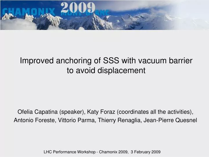
Improved anchoring of SSS with vacuum barrier to avoid displacement. Ofelia Capatina (speaker), Katy Foraz (coordinates all the activities), Antonio Foreste, Vittorio Parma, Thierry Renaglia, Jean-Pierre Quesnel. LHC Performance Workshop - Chamonix 2009, 3 February 2009. Overview.

E N D
Improved anchoring of SSS with vacuum barrier to avoid displacement Ofelia Capatina (speaker), Katy Foraz (coordinates all the activities), Antonio Foreste, Vittorio Parma, Thierry Renaglia, Jean-Pierre Quesnel LHC Performance Workshop - Chamonix 2009, 3 February 2009
Overview • Introduction • Initial requirements and actual SSS supporting • Updated requirements and improved supporting design • Planning and costs • Next weak point? • Conclusion O. Capatina EN/MME et al., Chamonix, 3rd of February 2009
Introduction • Incident on 19th of September 2008 => failure of some supports of SSS in sector 3-4 due to longitudinal loads O. Capatina EN/MME et al., Chamonix, 3rd of February 2009
Initial requirements and actual SSS supporting • Each SSS is installed on 1 jacks for longitudinal alignment + 2 for transversal alignment; The 3 jacks are used for vertical alignment O. Capatina EN/MME et al., Chamonix, 3rd of February 2009
Initial requirements and actual SSS supporting • Alignment done by geometers after installation O. Capatina EN/MME et al., Chamonix, 3rd of February 2009
Initial requirements and actual SSS supporting • Each SSS is installed on 1 jacks for longitudinal alignment + 2 for transversal alignment; The 3 jacks are used for vertical alignment O. Capatina EN/MME et al., Chamonix, 3rd of February 2009
Initial requirements and actual SSS supporting • Vacuum sectorisation for one LHC sector • Vacuum barrier in 13 SSS / sector (Q11R&L, Q15R&L, Q19R&L, Q23R&L, Q27R&L, Q31R&L, Q33R) • A total of 104 SSS with vacuum barrier O. Capatina EN/MME et al., Chamonix, 3rd of February 2009
Initial requirements and actual SSS supporting • Vacuum vessel/vacuum barrier designed for 0.15 MPa internal pressure • Supporting system should withstand loads induced by differential pressure on both sides of vacuum barrier: • Nominal operation: up to Δp = 0.1 MPa • Exceptional : up to Δp = 0.15 MPa • Δp = 0.1 MPa across vac. Barrier 80 kN at the jacks (tested value) jack O. Capatina EN/MME et al., Chamonix, 3rd of February 2009
Initial requirements and actual SSS supporting • Supporting system should withstand • Nominal operation up to 80 kN longitudinally (≡ 0.1 MPa) • Exceptionaloperation up to 120 kN longitudinally (≡ 0.15 MPa) • Actual SSS supporting system: • Designed for 80 kN and tested in the tunnel for a longitudinal load up to 90 kN • Test done once in surface building up to 120 kN (not documented) Sonia Bartolome et al., tests done in the LHC tunnel, June 2003 O. Capatina EN/MME et al., Chamonix, 3rd of February 2009
Initial requirements and actual SSS supporting • Actual SSS supporting system: • Tested failure tensile loads of anchors120 kN to150 kN • Ok for nominal operation • Failure limit for exceptional conditions (~ 150 kN) • No concrete damage observed Sonia Bartolome et al., tests done in the LHC tunnel, June 2003 O. Capatina et al., Chamonix, 3rd of February 2009 O. Capatina EN/MME et al., Chamonix, 3rd of February 2009
New configuration on warm sectors: 12 DN200, 4 DN100, 2 DN90 New configuration on cold sectors: 13 DN100, 2 DN90, 4 DN63 Updated requirements and improved SSS supporting • Sect.3-4 incident: estimate (see pres. Ph. Lebrun session 01) pressure inside vessels (on one side of vacuum barrier): 0.7 MPa (x 4.6 design pressure) => Improvements of security relief valves proposed (see pres. V. Parma session 04) different form warm / cold sectors • Updated design pressure (see pres. V. Parma session 04) (DP: Design Pressure) New design pressure L. Tavian O. Capatina EN/MME et al., Chamonix, 3rd of February 2009
Updated requirements and improved SSS supporting • Updated design pressure 0.3 MPafor SSS anchoring. Why? • Covers an important area of possible events • Very high but feasible value of longitudinal loads to be considered for the new anchor design - 240 kN; • The chain of elements vacuum barrier / cold foot / jack should be equilibrated • Design of vacuum barrier for 0.15 MPawith security factor 3 => confident that it withstands 0.3 MPa • Cold foot tests showed no failure up to 70 kNequivalent to 0.3 MPa jack O. Capatina EN/MME et al., Chamonix, 3rd of February 2009
Updated requirements and improved SSS supporting • Requirements for the design of the improved SSS anchors • Withstand longitudinal load of 240 kN • Possibility to install the system on SSS already on jacks • Reduced space under the SSS – very difficult for drilling • Accessibility for alignment • Estimation of realignment every year • Allow thermal contraction of vacuum tank in case of accident • Allow space for other foreseen equipment under the SSS • Uninstalling the system should allow SSS removal if needed • Transport / installation zones to be taken into account • Optimize price • Feasibility within general planning O. Capatina EN/MME et al., Chamonix, 3rd of February 2009
Updated requirements and improved SSS supporting • Several solutions have been studied • 1st solution – distribution of the longitudinal load among the 3 jacks O. Capatina EN/MME et al., Chamonix, 3rd of February 2009
Updated requirements and improved SSS supporting • Several solutions have been studied • 1st solution – distribution of the longitudinal load among the 3 jacks • No cryostat thermal contraction allowed O. Capatina et al., Chamonix, 3rd of February 2009
Updated requirements and improved SSS supporting • 2nd solution – bloc additional fixation to the ground – only shear loads transmitted to the floor • Poor accessibility to jacks for alignment O. Capatina et al., Chamonix, 3rd of February 2009
Updated requirements and improved SSS supporting • 3rd solution – bloc additional fixation to the ground and to the cryostat – only shear loads transmitted to the floor • Necessitates special installation procedure (monitored by geometers) to avoid vacuum tank deformation O. Capatina et al., Chamonix, 3rd of February 2009
Updated requirements and improved SSS supporting • 4rd solution – the final one O. Capatina EN/MME et al., Chamonix, 3rd of February 2009
Updated requirements and improved SSS supporting • Final solution – equivalent stress O. Capatina EN/MME et al., Chamonix, 3rd of February 2009
Updated requirements and improved SSS supporting • Final solution – deformation O. Capatina EN/MME et al., Chamonix, 3rd of February 2009
Updated requirements and improved SSS supporting • Final solution – reaction loads • Contact onsingle jackguaranteed O. Capatina EN/MME et al., Chamonix, 3rd of February 2009
Updated requirements and improved SSS supporting • Final solution – reaction loads • Ground fixation system tested this morning in SX4 O. Capatina EN/MME et al., Chamonix, 3rd of February 2009
Updated requirements and improved SSS supporting • Final solution – one ground fixation system tested in SX4 • Up to 380 kN applied longitudinally and 230 kN applied vertically (traction) during 10 min (1.5 x design load if only one side charged) => no visible damage observed M. Guinchard and A. Foreste, tests done in SX4, February 2009 O. Capatina EN/MME et al., Chamonix, 3rd of February 2009
Planning considerations • Prototype • Manufacturing complete prototype w7-8 • Test prototype w9 • LHC installation • Hypothesis • Conservative hypothesis that drilling not allowed when liquid helium • Installation = same risk as alignment operations (ok with liquid helium) • Drilling 2 weeks / sector starting in week 11 for sector 2-3 • Overall installation 2 weeks / sector within the general planning • Alignment check of SSS after system installation: a total of 25 days ok with general planning O. Capatina EN/MME et al., Chamonix, 3rd of February 2009
Costs • 104 systems to be manufactured and installed • System: 104 x 5’000 CHF 520’000 CHF • Ground fixation: 42’000 CHF • Manpower • Drilling: 104 x 4 x 6 x 62 CHF 155’000 CHF • Installation: 104 x 2 x 8 x 62 CHF 103’000 CHF • Equipment for drilling and installation: 27’000 CHF • Alignment: 20’000 CHF • Total for 8 sectors 867’000 CHF • Rmq transport operations not included O. Capatina EN/MME et al., Chamonix, 3rd of February 2009
Next weak point? • The anchoring of SSS with vacuum barrier have been discussed • If new cryostat design pressure 0.3 MPa instead of 0.15 MPa, what about the other equipments? • DFBA O. Capatina EN/MME et al., Chamonix, 3rd of February 2009
Next weak point? • DFBA • Calculations done by A. Bertarelli in 2006 for a vessel design pressure of 0.15 MPa absolute (0.05 MPa relative) • The new design pressure of 0.3 Mpa (0.2 MPa relative) multiplies the applied loads by a factor 4 • Shuffling module vacuum vessel – with the new design pressure the tank will plastify locally but should not get to failure • The “negative fixator” (external support) will fail • Fixation very difficult to improve due to lack of space Alessandro BertarelliDFBA calculations done in 2006 O. Capatina EN/MME et al., Chamonix, 3rd of February 2009
Conclusions • The design of the improved anchoring of SSS with vacuum barrier has been presented • It was designed to withstand 240 kN longitudinally, equivalent to 0.3 MPa of differential pressure on both sides of the vacuum barrier • The system is foreseen to be installed in “warm” sectors too as an additional safety device • The installation of the equipments will be within the global planning • The total cost will be of about 867’000 CHF, transport not included • Open questions • What happens if Δp > 0.3 MPa ? : cold foot, vacuum barrier damaged before external anchoring damage… • We are very confident that vacuum barrier and cold foot withstand the load equivalent to 0.3 MPa but it has never been demonstrated • Next week point could be the DFBA… • What about other elements (such as all “special” cryostats of the LSS, jumper vacuum barrier …)? O. Capatina EN/MME et al., Chamonix, 3rd of February 2009
Thank you ! … in particular Lucio for his patience and advices O. Capatina EN/MME et al., Chamonix, 3rd of February 2009