Download
1 / 15
160 likes | 219 Views
Project: IEEE P802.15 Working Group for Wireless Personal Area Networks (WPANs) Submission Title: [ C-band satellite interference measurements at TDK RF test range ] Date Submitted: [ 12 January, 2004 ] Source: [ Presenter 1: Evan Green ] Company [ Intel ]

E N D
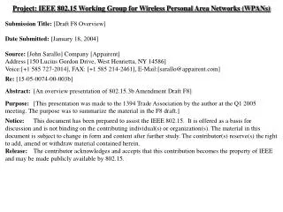
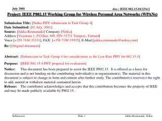
Project: IEEE P802.15 Working Group for Wireless Personal Area Networks (WPANs) Submission Title: [C-band satellite interference measurements at TDK RF test range] Date Submitted: [12 January, 2004] Source: [Presenter 1:Evan Green] Company [Intel] [Contributor 3: Gerald Rogerson] Company [General Atomics] [Contributor 4: Bud Nation] Company [Intel] Address [2111 NE 25th Ave, Hillsboro, OR 97124 MS: JF3-213] Voice:[503-264-8456], FAX: [503-264-3483], E-Mail: [evan.r.green@intel.com] Abstract: [This document describes UWB interference testing to C-band satellite TV receivers] Purpose: [For peer review and discussion regarding interference and regulatory issues] Notice: This document has been prepared to assist the IEEE P802.15. It is offered as a basis for discussion and is not binding on the contributing individual(s) or organization(s). The material in this document is subject to change in form and content after further study. The contributor(s) reserve(s) the right to add, amend or withdraw material contained herein. Release: The contributor acknowledges and accepts that this contribution becomes the property of IEEE and may be made publicly available by P802.15. Evan Green, Intel, et al.
Test Objectives and Facility • Objectives: • Measure interference potential to C-band TV service • FSS C-band 3.7-4.2GHz • Compare WGN, MB-OFDM & Impulse UWB signals • Investigate relative interference threshold • Determine safe distance from dish antenna to avoid interference • Test facility • Measurements conducted at outdoor RF test range • TDK RF test facility in Austin, TX • Tests conducted Dec 8-18, 2003 • Satellite TV reception system installed by Austin area provider • Dish size selected by provider as typical for the area Evan Green, Intel, et al.
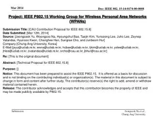
Test setup • Figure 1 on next page depicts the equipment configuration • Satellite TV reception system • C-band system with auto positioning dish • 10 foot Sami dish selected by provider as typical for Austin area • Motorola DSR-922 receiver selected due to popularity • UWB test transmitters • MB-OFDM 528MHz bandwidth, 3 band mode w/ zero CP • 3MHz PRF impulse mode • WGN generator used to emulate a DSSS system • RF distribution circuits provide • High isolation coaxial switch used for quick A/B comparison • Amplifier compensates for loss in 100’ coax feed line • Calibrated attenuators used to set power levels accurately • Directional couplers used for signal observation only Evan Green, Intel, et al.
Test equipment setup Wisair UWB TX C-band receiver AWGN source RF switch & distribution Variable attenuator Evan Green, Intel, et al.
MB-OFDM WaveformF1F2F3 Evan Green, Intel, et al.
Discone UWB antenna gain 2dBi broadside antenna gain Broadside orientation used in tests Evan Green, Intel, et al.
Test System Calibration • Attenuators enable power changes accurate to less than 0.1dB • Step attenuators calibrated to NIST traceable standard • Variable attenuator checked with thermal power meter (traceable) • UWB field strength • Set to FCC level using EIRP method • Measured with spectrum analyzer per FCC rules • 1MHz RBW, RMS detector, Peak hold • TX power measured at antenna connection • Compensates for loss in 100’ transmission line • Power set to -43.3dBm/MHz within satellite receiver bandwidth • 2dBi antenna gain brings EIRP to -41.3dBm/MHz (FCC) • All UWB generators set to the same power level • No backoff for frequency duty cycle Evan Green, Intel, et al.
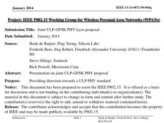
Receiver Operating Point • Several methods attempted, final method described here • Dish azimuth and elevation adjusted for maximum signal power • Adjustment improved signal by 0.5dB above automatic positioner • Elevation increased to reduce signal power • Pointing away from satellites • Signal power set to minimum for error free video • This is receiver minimum sensitivity point • Signal power fell by 2.5dB (operating margin) • Elevation was adjusted to set receiver operating points • 2.5dB, 1.0dB & 0.5dB above sensitivity Evan Green, Intel, et al.
2.5dB Receiver operating point Maximum signal power Receiver input signal Fc = 990MHz = 5150 - 4160 5150MHz (LO) 4160MHz (C-band signal) Signal power at minimum sensitivity Evan Green, Intel, et al.
Relative Interference Measurement • Satellite Galaxy 1R (G1) • Channel MMAXW, fc=4.16GHz • Digicipher II stream (QPSK, 7/8 FEC, 29.27Ms/s) • UWB antenna placed within 20° elevation of dish boresight • RF power of AWGN and MB-OFDM calibrated (each time) • RF switch set to AWGN signal and attenuators set to the threshold of visible artifacts in the video • RF switch set to MB-OFDM and signal power reduced to find the threshold of visible artifacts in the video • Above procedure repeated for AWGN vs. Impulse UWB • Record power changes by reading variable attenuator only • Most accurate method for relative power indication Evan Green, Intel, et al.
Interference threshold MeasurementsdB relative to AWGN Evan Green, Intel, et al.
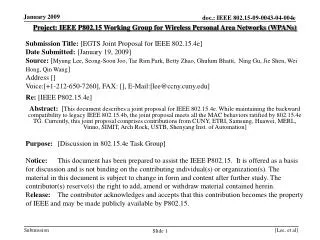
Safe Distance Measurements • Satellite selected Galaxy 1R (G1) • Channel MMAXW, fc=4.16GHz • Digicipher II stream (QPSK, 7/8 FEC, 29.27Ms/s) • UWB antenna placed within 20° elevation of dish boresight at furthest distance • RF power of AWGN and MB-OFDM calibrated per procedure above (each test) • RF switch set to AWGN signal and antenna moved closer to the dish to find the interference threshold; mark with red flag • RF switch set to MB-OFDM and antenna moved away to find the threshold of artifacts; mark with green flag • Above repeated at different azimuth angles relative to the dish • Above repeated for AWGN vs. Impulse UWB using blue flags Evan Green, Intel, et al.
Safe Distance Measurements MB-OFDM WGN Dish Orientation Scale in feet Evan Green, Intel, et al.
Safe Distance Measurements Red flags mark WGN Green flags mark MB-OFDM Evan Green, Intel, et al.