Download
1 / 6
60 likes | 68 Views
This document provides instructions for capturing and simulating the memory controller element in an applied VHDL project. It includes an overview of the project, block diagram, and assignment instructions.

E N D
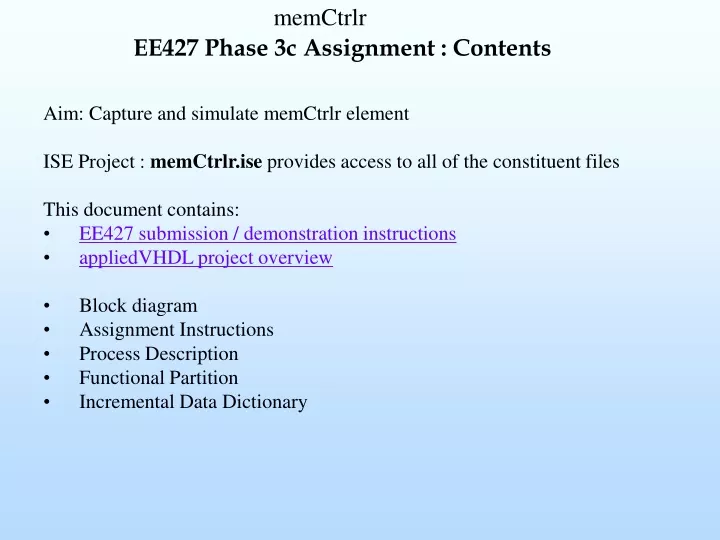
EE427 Phase 3c Assignment : Contents • Aim: Capture and simulate memCtrlr element • ISE Project : memCtrlr.ise provides access to all of the constituent files • This document contains: • EE427 submission / demonstration instructions • appliedVHDL project overview • Block diagram • Assignment Instructions • Process Description • Functional Partition • Incremental Data Dictionary
DFD 1.3 (memCtrlr)Block diagram Block Diagram: symbol DFD 1.3.1 SRAM SpecramBFM
Assignment instructions memCtrlr • Review/verify/complete memCtrlr.vhd • Synthesise and view RTL schematic. Confirm correctness. • Simulation is not required. Simulation has been performed at the memCtrlrUnit level • FPGA implementation is not required
DFD 1.3 (memCtrlr) Process Description • In addition to memCtrlrUnit design functionality • Supports two sources of RAM r/w access (IOCSRBlk and dspBlk. Source selected by signal dspActive • Timing assumption : dspRamAdd and IORamAdd are stable when memCtrlr is activated • Selects RAM wr data from datCtrlr or dspBlk (using dspActive) • Selects RAM addr from CSR(2:0) bytes or dspBlk (using dspActive)
DFD 1.3 Incremental Data Dictionary ramWr : flag indicating IO or DSP ram write request ramRd : flag indicating IO or DSP ram read request dat2Ram(31:0) : 32 bit (IO or DSP) subsystem data to be written to RAM ramAddSrc(17:0) : 18 bit RAM address (from IO or DSP subsystem). Max RAM address is 256k