Download
1 / 17
170 likes | 458 Views
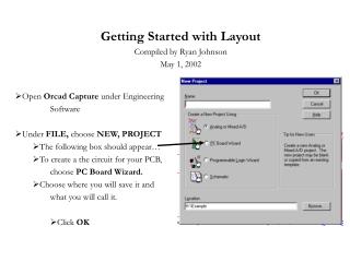
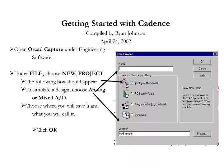
Getting Started with Cadence Compiled by Ryan Johnson April 24, 2002 Open Orcad Capture under Engineering Software Under FILE, choose NEW, PROJECT The following box should appear… To simulate a design, choose Analog or Mixed A/D. Choose where you will save it and

E N D
Getting Started with Cadence Compiled by Ryan Johnson April 24, 2002 Open Orcad Capture under Engineering Software Under FILE, choose NEW, PROJECT The following box should appear… To simulate a design, choose Analog or Mixed A/D. Choose where you will save it and what you will call it. Click OK
In the next box, choose if you want to create a blank project or one based on an existing project. • Click OK. • A blank schematic page will appear. This is where you will draw your schematic. • Important: Notice that there is a PSpice menu on the menu bar. If this is not there, you will not be able to simulate your circuit.
When you create a new project, a window will appear that shows the design hierarchy. This is where you can access all the files associated with your project. It keeps a list of things such as: • Schematics • Parts used • Simulation profiles • Libraries used • Etc… • To get to this window from your schematic, choose the Window toolbar and then choose the name of the project you want to view (*.opj)
Getting Familiar with the Toolbars • The top of the schematic page will have the following toolbar: • Zoom buttons are here: • The parts that you use will be listed here for easy access: • These buttons are used for measurements on your schematic during simulations: • These buttons are used for creating a new simulation profile, changing the profile characteristics, and running your simulation:
This toolbar gives shortcuts for building the circuit. • Place a part button: • Draw a wire button: • Place power node button: • Place GND button:
Circuit Creation • To place a part on your schematic, in Place menu, choose Part. The following box will appear… • You have to add the specific libraries to your project of the parts you will use. • Choose Add Library
The libraries that contain parts that will allow you to simulate are found in folders labeled PSpice. • These parts have PSpice model attributes with them. • Choose the libraries that you want to add. • Sometimes it is hard to know what library parts are in. If you know the name of the part that you want, you can also search for the part.
The parts found in the library are listed here: Select the part that you want to place. • Your project profile will keep a record of each type of part you use in a place called Design Cache.
To change the values of the parts, double click on the part. The following page should appear: • To view only the Spice (or simulation) properties of the components, change this box to Orcad-PSpice. Once done, the page will only show the parameters that affect simulations. Change the value of the component, click Apply, and exit the page.
While you place your parts, use the wire button to place wires. It is found on the right-hand side toolbar. Make sure that you have good connections. • Cadence is really picky about which GND you use when simulating a circuit. To get this GND, choose the GND button. The following box should appear where you can add a library that contains the proper GND. The library should once again come from the PSpice folder as these parts have simulation attributes with them. The best way to know that you have the right one is by checking if it has a zero next to it.
If you need to change the internal parameters of the component, click on the component so that it is highlighted. Under the Edit menu, choose PSpice Model. The following widow should appear. Change the parameters that need to be changed, and then save it. This will force the same parameters for this type of component in this project. Next time that you use this piece in this project, it will have these changed parameters.
There are a couple of different ways to check for errors in your circuit. The first is by creating a netlist. • Under the PSpice menu, choose Create Netlist. • You can view the netlist by choosing View Netlist, under the same PSpice menu. • The next way is to actually simulate the circuit. • To simulate, you need to create a new simulation profile. Under the PSpice menu, choose New Simulation Profile. The following window will appear so that you can name it. You can also choose which schematic you want it to associate with.
Once you have named it, click OK, and the following simulation settings widow will pop up. This is where you choose what you want to do when you simulate. • In this menu, you can choose what type if simulation to do (Transient, DC Sweep, AC Sweep, or Bias Pt) • There are options for each type of simulation. • If you want to restore your last simulation data points, you would click to this menu. The last simulation will not be overwritten. • Once you have everything figured to how you want it, click OK. To simulate, you need to push the play button.
Once you push Run, the following widow will appear as Spice checks for errors and completes the simulation.
Then, the simulation results will appear. • If you have measurement markers placed on the circuit, the waveforms will appear. If not, then you need to tell Spice which results to display. • To do this, in Spice choose Trace, Add Trace. The following window will appear. Choose the results you would like to view.
Sample Circuit (with Sample Simulation)