Download
1 / 25
270 likes | 766 Views
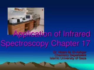
The JWST Mid-Infrared Instrument: MIRI. Margaret Meixner MIRI Science Team Member MIRI instrument support scientist Based on Slides presented by the MIRI team as noted. Optics Module (including Thermal Strap Assembly). OM Stage (6K heat exchanger(s). FSW.

E N D
The JWST Mid-Infrared Instrument: MIRI Margaret Meixner MIRI Science Team Member MIRI instrument support scientist Based on Slides presented by the MIRI team as noted.
Optics Module (including Thermal Strap Assembly) OM Stage (6K heat exchanger(s) FSW “Heat Sink Assy” (Recuperator, valves) FPE ICE RLDA (part of CTA) Coldhead Environmental Shield JT Pre-cooler Recuperator 3-Stage Pulse Tube Pre-cooler Coldhead Precooler Compressor JT Compressor Relay Switch Assembly Cooler Control Electronics MIRI System Flight Components (Goodson & Renouf& Larson) • Plus the following Harnesses that mounted to ISIM: • OM to ICE Harnesses • OM to FPE Harnesses • Cryo-cooler to FPE Harnesses Cooler
MIRI OM, Cooler and ISIM (Larson) • OMS will mount at the Thermal Strap assembly interface to the OM Primary Structure lower deck component • Figure shows notional Heat Exchanger mounted to TSA thermal interface • Heat exchanger position is well inside MLI support structure and MLI • Cooler refrigerant line treated like harness • One or more standoff brackets designed to accept P-clip or similar conventional attachment (green item in right figure below) Refrigerant line support OMS Preliminary refrigerant line routing Notional HSA
Overview MIRI Cooler TRL-6 Plan (Larson) Technology to be Demonstrated: Operation of the 6K Cooler system in JWST environment at JWST performance levels TRL-6 Item Description: Engineering grade Cooler components: Cold Head (remote), field joints, compressor(s), and pre-cooler cold end, with DM drive electronics Key Items to be Proved: Performance: Base temperature under remote heat load, leak rate, gas purity, cooling efficiency, noise, exported vibration Environment: Cryogenic operating temperatures, applied heat loads, vibration, radiation • Current Status: • - Current TRL is 4 to 6 depending on component • - Technology development program has proven: • Remote cooling capability • Cooler compressor(s) • - Cooler vendor selection is complete and on contract
Instrument Functions (Wright) • Multiple Optical Configurations • Photometric Imaging over a wide field. • Coronagraphy between 10 and 27 mm. • Low Resolution (R = 100) Slit Spectrosopy of Single Sources (5 – 10 mm). • Medium Resolution (~ 100 km/sec velocity resolution) Integral Field Spectroscopy from 5 to 28.5 mm. • Diffraction limited image quality. • To maximise the sensitivity on point sources. • To exploit JWST’s spatial resolution (resolve ~ 1 kpc at all redshifts). • Optimised Sensitivity The minimum noise level is bounded by the instrument environment (thermal emission from the sky and telescope), so MIRI must • Have high Photon Conversion Efficiency (Optical Transmission x Detector QE). • Spatial and Spectral Passbands matched to the science targets.
MIRI Allocation 4QPM 15.5µm MIRIM FOV 4QPM 11.4µm Imager 4QPM 10.65µm Lyot Mask 23mm Low Resolution Spectrometer Medium Resolution Spectrometer MIRI Fields of View (Glasse)
1.7 arcmin 1.3 arcmin Imager - Optical Requirements (Wright) Design: Requirements: • > 2 square arcmin field of view, with a 0.11 arcsecond pixel scale • Image Quality • > 58% of light within first dark ring of model telescope PSF • Strehl ratio > 85 % longward of 5.6 mm • Coronagraphy in 4 filter bands (see Design Doc. for details) • R=100 Spectroscopy Simulated NIR JWST field (Myungshin Im 1998)
Focal plane M1 M2 Filters Cold stop M3 M4 Detector M5 270 mm The MIRI Imager (Glasse) • Coronagraphic masks and a slit for low resolution spectroscopy are mounted in the telescope focal plane. • The filter wheel includes the 10 imaging filters, 4 coronagraphic filter/pupil mask combinations and a prism.
monochromatic coronagraphs 4 masks in focal plane Lyot diaph. + 23 µm filter 4Q diaph. + 11.4mm filter 4Q diaph. + 10.65mm filter 4Q diaph. + 15.5 mm filter ND (l/dl = 20) (l/dl = 20) (l/dl = 5) (l/dl = 20) Implementation (Boccaletti)
Low Resolution Spectrograph, LRS (Meixner) • 5-10 m coverage • R~100 at 7.5 m • Double prism in filter wheel LRS 5 0.6
Each channel’s field of view is sliced, dispersed and detected. Channel 1 (4.9 - 7.7 mm) Channel 2 (7.4 - 11.8 mm) Channel 3 (11.4 - 18.2 mm) Channel 4 (17.5 - 28.8 mm) Wavelength/Velocity Medium Resolution Spectrometer - Format (Wright) REQUIREMENT - Integral Field Spectroscopy with > 3 arcsec field of view from 5 to 28.5 µm. 10 arcseconds
Collimator Grating Camera 1 FPA 1 IFU 1B Collimator Grating SWdichroic IFU 1A centre dichroic IFU 2A Collimator Grating IFU 2B LW dichroic Camera 2 FPA 2 Collimator Grating The MRS concept (Wells)
MIRI OBA - Medium Resolution Spectrometer (Glasse) • The Spectrometer has two arms, each with its own FPM. • Each spectrometer arm is further divided into 2 channels. • Two mechanisms present gratings and dichroics which cover the full 5 to 28 micron wavelength range by rotation between three positions. Channel 3 IFU Image Slicer Channel 1 Channel 2 Channel 4 Dichroic/grating wheel Focal Plane Module
Spectrometer Eng. Qualification Hardware (Glasse) • A dichroic wheel • An image slicing mirror
MIRI MRS - Spectral Coverage (Glasse) • The MRS covers the 5 to 28 micron range in 12 sub-spectra Spectral Resolving Power FRD 2.5.1.2 How the spectra will appear on the MRS’s two detectors Wavelength [mm]
Pretty Hardware Pictures – Ressler “Front” side of FPM showing installed detector assembly. “Back” side showing connector and thermal strap attachment point.
QE, Ressler QE exceeds requirement at all wavelengths < 23 microns. MIRI Science Team has accepted this performance with the understanding that there willbe a reduced sensitivity margin in the 25.5 micron filter.
Nearing TRL 6 Completion • “System/subsystem model or prototype demonstration in a relevant environment (ground or space)” • MIRI Sensor Chip Assemblies (SCAs) or representative models must be proven to be at TRL 6 • 6 key measurements: • QE • Dark Current • Read Noise • Radiation Immunity • Vibration Levels • Thermal Cycling
Sensitivity Requirements (Ressler) • Ultimately bounded by the flux of background radiation from the sky and telescope. JWST Background [photon s-1mm-1 arcsec-2] 106 OTA 105 Sunshield 104 Zodiacal Dust 103 5 10 15 20 25 Wavelength [micron]
MIRI Team (Meixner) • MIRI Science Team: George Rieke (U of Az/lead) • US: George Rieke (U of Az/lead), Michael Ressler (JPL/Proj. Sci), Margaret Meixner (STScI), Tom Greene (NASA/Ames) • Europe (members rotate): Gillian Wright (UK ATC/co-lead), Torsten Boeker (ESA), Ewine van Dishoeck (Leiden/Netherlands), Christoffel Waelkens (Leuven/Belgium) • MIRI Engineering Leads: • US: Graham Bothwell (JPL/Project Manager); Greg Goodson (JPL/Systems Engineer), Phil Driggers (Goddard/Instrument Manager) • Europe/ESA: Andrea Marini (ESA/PM), John Thatcher (PM/Astrium), Ian Renouf (Systems Engineer) • MIRI Team at STScI: • Margaret Meixner & Scott Friedman MIRI Instrument Scientists • Jerry Kriss: JWST/ISIM lead • Vicki Balzano & Michael Robinson: MIRI operations and flight software support
MIRI Milestones (Meixner) • MIRI PDR: March 17&18 2005; passed • Detector TRL 6, June 2006 • MIRI CDR: September 2006 • Cooler TRL 6, January 2007 • JWST launch: >2013 Fomalhaut MIRI Spitzer