Download

1 / 37
370 likes | 579 Views
Automatic Verification of a Turbogas Control System with the Murphi Verifier. Enrico Tronci Computer Science Department, University of Rome “La Sapienza”, Via Salaraia 113, 00198 Roma, Italy, tronci@dsi.uniroma1.it , http://www.dsi.uniroma1.it/~tronci Joint work with:

E N D
Automatic Verification of a Turbogas Control System with the Murphi Verifier Enrico Tronci Computer Science Department, University of Rome “La Sapienza”, Via Salaraia 113, 00198 Roma, Italy,tronci@dsi.uniroma1.it, http://www.dsi.uniroma1.it/~tronci Joint work with: G. D. Penna, B. Intrigila, I. Melatti, M. Minichino, E. Ciancamerla, A. Parisse, M. Venturini Zilli HSCC03: Hybrid Systems: Computation and Control, Prague, The Czech Republic, April 3-5, 2003
Automatic Verification Game Given: a Hybrid Systems S and an undesired state BAD (e.g. an error state) We want to know: under which conditions, if any, our system S can reach BAD during its evolution.
HOW System Model + Param. Ranges + Disturbances Requirements (undesired/desired states) Init States Model Checker Yes I.e. no sequence of events (states) can possibly lead to an undesired state. Counterexample I.e. sequence of events (states) leading to undesired state.
Example (Simulation 1) x(t + 1) = if x(t) <= 3 then x(t) + u(t) else x(t) – u(t), u(t) = 1, 2. x(0) = 0 2 1 3 0 1 1 1 1 1 2 2 2 4 2 Sim length: 10 1, 2, 1, 2, 1, 1, 2, 2, 2, 1 2 Spec: x(t) < 5. I.e. no state with x(t) >= 5 is reachable. Spec does not fail on this run
Example (Simulation 2) x(t + 1) = if x(t) <= 3 then x(t) + u(t) else x(t) – u(t), u(t) = 1, 2. x(0) = 0 1 3 2 2 0 1 5 1 1 2 4 2 Sim length: 6 1, 2, 1, 2, 1, 2 Spec: x(t) < 5. I.e. no state with x(t) >= 5 is reachable. Spec FAIL
Example (Model Checking) x(t + 1) = if x(t) <= 3 then x(t) + u(t) else x(t) – u(t), u(t) = 1, 2. x(0) = 0 2 1 3 2 2 0 1 5 1 1 1 1 2 1 2 2 4 2 Spec: x(t) < 5. I.e. no state with x(t) >= 5 is reachable. Spec FAIL Spec ok if u(t) = 0, 1.
A Larger System x(t + 1) = case x(t) – 2 + u(t) when x(t) + y(t) > 4 x(t) – 1 + u(t) when x(t) + y(t) = 4 x(t) + u(t) when x(t) + y(t) = 3 x(t) + 1 + u(t) when x(t) + y(t) = 2 x(t) + 2 + u(t) when x(t) + y(t) < 2 esac y(t + 1) = u(t) u(t) = -1, 0, 1 x,y 1,-1 2,-1 3,-1 -1 0 0,0 2,0 3,0 4,0 1 3,1 4,1 5,1
Remark • MC and Simulation have different, complementary goals. • MC from the system model AND state X produces a sequence of stimuli (events) j, if any, leading to state X. (Obstrucion: State Explosion) • Simulation from the system model AND a sequence of stimuli (events) j shows where j leads (in | j | steps). (Obstrucion: False Negatives). .
Model Checking as State Space Exploration For safety properties (no bad state is reachable) the model checking problem becomes the reachability problem on the transition graph of the system to be analyzed. Given a Finite State System S = (S, I, Next), where: S : Finite set of states; I : set of initial states; Next : function mapping a state to the set of its successors; Visit all states that S can reach from I.
Model Checking Flavors Explicit Set Reach of visited states stored in a Hash Table. Explicit approach typically works well for protocols, hybrid systems and software-like systems (i.e. asynchronous systems). Famous MC: SPIN (Bell Lab), Murphi (Stanford). Symbolic Set Reach of visited states represented with its characteristic function f. That is f(s) = if (s is in Reach) then 1 else 0. States are bit vectors, thus f is a Boolean function. Ordered Binary Decision Diagrams (OBDDs) are used to efficiently represent and manipulate f. Symbolic approach typically works well for Hardware-like systems (i.e. synchronous systems). Famous MC: SMV (CMU), VIS (CU + Berkeley), CUDD (CU).
Overview Symbolic model checkers are typically used for automatic verification of Hybrid Systems. We present a nontrivial case study on automatic verification of a Hybrid Systems using an explicit model checker. Namely, Automatic verification with Murphi verifier of the Turbogas Control System of a 2MW Co-generative Power Plant (ICARO). Our experimental results show that explicit model checkers (Murphi in our case) can outperform symbolic model checkers for verification of Hybrid Control Systems.
History • Murphi is an explicit state model checker for low level analysis of Protocols and Software-like Systems. • Murphi has been realized Alan Hu, David Dill, Ulrich Stern, and many others from University of Stanford, USA. • Murphi: http://sprout.stanford.edu/dill/murphi.html • Cached Murphi has been obtained from Murphi by changing Murphi engine so as to use a cache based BFS and by adding finite precision real numbers. Cmurphi 4.2 uses a disk based BFS. • Cached Murphi is a joint effort of the University of L’Aquila and at the University of Rome “La Sapienza”. • Cached Murphi: http://www.dsi.uniroma1.it/~tronci
PLAN • Add finite precision real numbers to Murphi. This allows easy modeling of (discrete time) Hybrid Systems. • Build model of ICARO Turbogas Control System. • Code model with Murphi verifier. • Run verification experiments.
A Simple SystemA glimpse of Murphi input language 0 2 0 2 1 3 0 2 0 1 5 1 1 1 1 2 1 2 4 2 0 0 0 2 x(t) + d(t) when x(t) <= 3 x(t + 1) = x(t) – d(t) when x(t) > 3 d(t) = 0, 1, 2. x(0) = 0
Murphi Code x(t + 1) = if x(t) <= 3 then x(t) + d(t) else x(t) – d(t) ; d(t) = 0, 1, 2 ; x(0) = 0; Spec: x(t) < 5 (FAIL). Spec: x(t) <= 5 (PASS). CONST -- constant declarations MAX_STATE_VALUE : 5; TYPE -- type declarations state_type : 0 .. 10; -- integers from 0 to 10 disturbance_type : 0 .. 2; VAR -- (global) variable declarations x : state_type; -- variable of type state_type -- next state function function next(x: state_type; d : disturbance_type): state_type; begin if (x <= 3) then return (x + d); else return (x - d); endif end; startstate "startstate" -- define initial state x := 0; end; -- nondeterministic disturbances -- trigger system transitions ruleset d : disturbance_type do -- define transition rule rule "time step" true ==> begin x := next(x, d); end; end; -- define property to be verified invariant"x less than 5" (x < MAX_STATE_VALUE);
Murphi Error Trace Startstate startstate fired. x:0 ---------- Rule time step, d:1 fired. x:1 ---------- Rule time step, d:2 fired. x:3 ---------- Rule time step, d:2 fired. The last state of the trace (in full) is: x:5 ----------
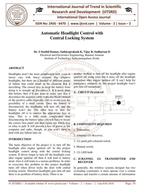
Gas Turbine System Disturbances: electric users, param. var, etc Settings Fuel Valve Opening FG102 Controller Gas Turbine (Turbogas) Vrot, Texh, Pel, Pmc Vrot: Turbine Rotation speed Texh: Exhaust smokes Temperature Pel: Generated Electric Power Pmc: Compressor Pressure
Controller Vrot: Turbine Rotation speed Texh: Exhaust smokes Temperature Pel: Generated Electric Power Pmc: Compressor Pressure Vrot N1Gov MIN Offset Pel PowLim 12MW ADJ Limiter ExTLim Winner Texh Valve FG102 Opening Command Pmc
B A A B Cell i Kp Cell Output + - 10MW S X + -10MW SAT - Ki 1/s P X SAT >0? Reset at u + 4kW u = min( output N1Gov, output PowLim, output ExTLim) AND Winner name Winner != i?
S Cell i = “Power Limiter” A = 3000kW B = 10Mw P Power Limiter (PowLim)Electric Power Controller Pel Setpoint (+2MW) Output PowLim Pel Winner Vrot: Turbine Rotation speed Texh: Exhaust smokes Temperature Pel: Generated Electric Power Pmc: Compressor Pressure
N1 Governor (N1Gov)Turbine Rotation Speed Controller Vrot: Turbine Rotation speed Texh: Exhaust smokes Temperature Pel: Generated Electric Power Pmc: Compressor Pressure Accelleration 1/s 105% Deceleration Output N1 Governor network 6% + Pel X - S Cell i = “N1 Governor” A = 0 B = 10MW isle Kdr P Vrot Winner
Exhaust Temperature Limiter(ExTLim)Exhaust Smoke Temperature Controller Texh Cell i = “Exhaust Temperature Limiter” A = 0 B = 10MW P Pmc + S Offset Winner Output Exhaust Temperature Limiter Vrot: Turbine Rotation speed Texh: Exhaust smokes Temperature Pel: Generated Electric Power Pmc: Compressor Pressure
Gas Turbine Disturbances: el. users, par. var, etc. Texh Gas Turbine FG102 Vrot Pel Vrot: Turbine Rotation speed Texh: Exhaust smokes Temperature Pel: Generated Electric Power Pmc: Compressor Pressure
Modeling • All subsystems are modeled as Finite State Automata (FSA). • This implies: • Time is discrete. • State values range on finite precision real numbers (namely real(4, 2): 4 digit mantissa, 2 digit exponent). Going to discrete time brings in a sampling frequency F = 1/T. dx(t)/dt = f(x(t), u(t)) (x(t + 1) – x(t))/T = f(x(t), u(t)) x(t + 1) = x(t) + T*f(x(t), u(t))
Gas Turbine (as seen from Controller) Generated Electric Power: P(t + 1) = P(t) + (a1(P(t) – P0) + a2FG102(t) – a3u(t))T Smokes Temperature: Tf(t + 1) = Tf(t) + (b1(P(t) – P0) + b2FG102(t) – b3u(t))T Turbine Rotation Speed: V(t + 1) = V(t) + (c1(P(t) – P0) + c2FG102(t) – c3u(t))T User demand u(t + 1) = u(t) + MAX_D_U *ud (t)*T MAX_D_U = Max variation speed (time derivative) of user el. demand ud (t) = -1, 0, 1 (uncontrolled load disturbance) Coefficients a, b, c computed by fitting with plant log data.
A Glimpse of the PI Model PI: dx/dt = K*u(t) Discrete Time PI: x(t + 1) = x(t) + K *u(t)*T
Murphi Code for GTS: const CONST SAMPLING_FREQ : 100.0; -- sampling frequency in Hz. -- Max Electric Power generated (kW) MAX_ELECT_POW_GEN_ALT: 3200.0; -- Max turbine rotation speed (percentage of max = 22500 rpm) MAX_ROT_SPEED: 130.0; MAX_ COMPR_PRES: 14.0; -- Max compressor pressure (bar) MAX_SMOKE_TEMP: 600.0; -- Max exhaust smokes temperature (C) -- Max variation speed (time derivative) of user demand MAX_D_U: 10.0; FREQ_1 : 100; -- frequency injection disturbances kdr : 0.0019; -- multiplier
Murphi Code for GTS: type TYPE -- define our real type: -- 4 digit mantissa, 2 digit exponents, ±0.mmmm*10±nn real_type : real(4,2); Pow_Gen_type: real_type; -- power generator type Rot_Speed_type: real_type; -- rot speed type Mode_type: 1 .. 2; -- 1 isle, 2 net -- exhaust smokes temperature type Smoke_Temp_type: real_type;
Murphi Code for GTS: var VAR -- Generated Electric Power (kW) Power : Pow_Gen_type; -- Turbine rotation speed (percentage of max = 22500 rpm) v_rot : Rot_Speed_type; -- Exhaust smokes temperature (C) smokes : Smoke_Temp_type; modality_value : Mode_type;-- 1 isle, 2 net
Murphi Invariants -- invariants invariant "power ok" (Power>=1300) & (Power<=2500); invariant "fumi ok" (smokes>=200) & (smokes<=580); invariant "rot speed ok" (v_rot>=40) & (v_rot<=120);
Murphi Output OK (MAX_D_U = 10.0) Cached Murphi Release 3.1 Finite-state Concurrent System Verifier. … Progress Report: ---- begin bfs level 0. … ---- begin bfs level 12903. ---- begin bfs level 12904. ========================================================================== Status: No error found. State Space Explored: 2246328 states, 6738984 rules fired in 16988.18s. Collision Rate: 1.9587522e-05. Levels Explored: 12904. Omission Probabilities (caused by Hash Compaction): Pr[even one omitted state] <= 4.8779e-08 Pr[even one undetected error] <= 2.62273e-10 Diameter of reachability graph: 12904
Murphi Output FAIL (Max_D_U = 25) ---- begin bfs level 0. … ---- begin bfs level 1533. The following is the error trace for the error: Invariant "rot speed ok, morsetto:2" failed. Startstate initstate fired. Power:+2.000e+03 v_rot:+7.500e+01 FUMI:+5.520e+02 N1_gov:+1.000e+03 Pow_lim:+1.000e+03 Temp_lim:+1.000e+03 valve_fg102:+1.000e-01 v:+7.500e+02 N1_state:+1.000e+03 Powlim_state:+1.000e+03 templim_state:+1.000e+03 minall:+1.000e+03 winner:2 step_counter:0 pressione:+1.200e+01 utenza:+0.000e+00 modality_value:1
Murphi Fail (2) Rule time step, morsetto:2, modalita:2, d_pressione:0, N1_d1:0, N1_d2:0, Powlim_d:0, templim_d:0, utenza_d:-1 fired. v_rot:+7.507e+01N1_gov:+1.100e+04 Temp_lim:+6.180e+03v:+1.050e+02 N1_state:+1.004e+03templim_state:+1.004e+03 step_counter:1 ---------- …. Rule time step, morsetto:2, modalita:2, d_pressione:0, N1_d1:0, N1_d2:0, Powlim_d:0, templim_d:0, utenza_d:-1 fired. The last state of the trace (in full) is: Power:+1.627e+03v_rot:+3.994e+01 FUMI:+5.520e+02N1_gov:+1.120e+04 Pow_lim:+1.199e+03Temp_lim:+6.380e+03 valve_fg102:+1.198e-01v:+1.050e+02 N1_state:+1.202e+03Powlim_state:+8.283e+02 templim_state:+1.202e+03minall:+1.199e+03 winner:2step_counter:34 pressione:+1.200e+01utenza:+1.250e+02 modality_value:2
Murphi Fail (3) End of the error trace. ===================================================== Result: Invariant "rot speed ok, morsetto:2" failed. State Space Explored: 1739719 states, 5186047 rules fired in 12548.25s. Collision Rate: 0. Levels Explored: 1533.
Experimental Results Results on a INTEL Pentium 4, 2GHz Linux PC with 512 MB RAM. Murphi options: -b, -c, --cache, -m350
Why does it work? Here we are interested in automatic verification of a control system in a neighborhood of its setpoint. A well designed controller keeps the whole system in a (small) neighborhood of the setpoint, thus the set of states that are reachable from the setpoint is small. An explicit model checker, like Murphi, can exploit this fact. Taking advantage of this fact, using a symbolic model checker may be hard. As a result, the representation of the system transition relation can be so large that we may run out of memory even before starting the reachability analysis. Indeed this was our experience when we tried to use HyTech and SMV on our hybrid system verification problem.
Conclusions • Finite Precision Real Numbers can be easily added to Murphi verifier. This allows easy modeling of hybrid systems with Murphi. • Nontrivial case study presented: Automatic Verification of Turbogas Control System of a Co-generative Electric Power Plant (ICARO). • Our experimental results suggest that Murphi can be effectively used for automatic verification of Hybrid Control Systems.