Download
1 / 2
30 likes | 220 Views
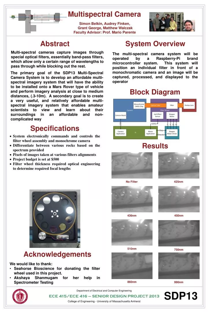
Multispectral Camera. Team Logo. Simon Belkin , Audrey Finken , Grant George, Matthew Walczak Faculty Advisor: Prof. Mario Parente. Abstract. System Overview.

E N D
Multispectral Camera Team Logo Simon Belkin, Audrey Finken, Grant George, Matthew Walczak Faculty Advisor: Prof. Mario Parente Abstract System Overview Multi-spectral cameras capture images through special optical filters, essentially band-pass filters, which allow only a certain range of wavelengths to pass through while blocking out the rest. The multi-spectral camera system will be operated by a Raspberry-Pi brand microcontroller system. This system will position an individual filter in front of a monochromatic camera and an image will be captured, processed, and displayed to the operator • The primary goal of the SDP13 Multi-Spectral Camera System is to develop an affordable multi-spectral imagery system that will have the ability to be installed onto a Mars Rover type of vehicle and perform imagery analysis at close to medium distances, (.3-10m). A secondary goal is to create a very useful, and relatively affordable multi-spectral imagery system that enables amateur scientists to view and learn about their surroundings in an affordable and non-complicated way Block Diagram Specifications • System electronically commands and controls the filter wheel assembly and monochrome camera • Differentiate between various rocks based on the spectrum provided • Pixels of images taken at various filters alignments • Project budget is set at $500 • Filter wheel thickness required optical engineering to determine required focal lengths Results No Filter 425nm 436nm 450nm 510nm 750nm Acknowledgements • We would like to thank: • Seahorse Bioscience for donating the filter wheel used in this project. • AkshayaShanmugam for her help in Spectrometer Testing 860nm 990nm Department of Electrical and Computer Engineering ECE 415/ECE 416 – SENIOR DESIGN PROJECT 2013 College of Engineering - University of Massachusetts Amherst SDP13
Optics and Ray Tracing Raspberry Pi • Extension tubes added to facilitate a greater focal length. • Thin lens equation, 1/di = 1/f – 1/do, determines the distance to the object, do, and to the image, di. Filter Selection Above are the important wavelengths that differentiate the rocks based on those values Getting Images via Image Registration Cost Accounting Development (R&D Costs) Image Registration is the process of estimating an optimal transformation between two images. We transformed a picture taken with filters based on a reference image taken without filters. The Software was done in python to work on the pi. Production Cost Geometric calibration was done in Matlabto remove geometric distortions caused by various filters. The images above were taken from Matlab while performing camera calibration. It shows the distortion model of images from filters and the settings of the camera at various filters