Download

1 / 26
300 likes | 547 Views
Multispectral Camera. Comprehensive Design Review Team Parente. Simon Belkin, Audrey Finken , Grant George, & Matthew Walczak. Problem. Scientists desire the ability to capture measurements based on reflected energy (radiance)

E N D
Multispectral Camera Comprehensive Design Review Team Parente Simon Belkin, Audrey Finken, Grant George, & Matthew Walczak
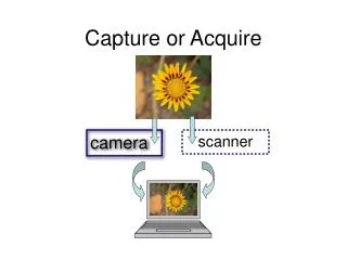
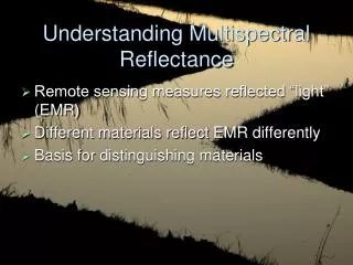
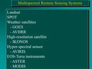
Problem Scientists desire the ability to capture measurements based on reflected energy (radiance) Common camera technology only captures light in three primary wavelengths: Red, Green, and Blue (RGB) from the visible spectrum of light
Solution Red = Bowline type rocks Green = Whittaker/Hillary (Jibsheet class) Blue = bright drift soil RGB = 450nm – 650nm
Deliverables Set at CDR • Build optical system • Camera can focus • Capture images at different distances • Aberration solution • Algorithm selected • Code in progress • Stepper motor control • Raspberry Pi control the stepper motor • Can turn clockwise and counterclockwise
Optical System • Out of focus condition due to the addition of filter wheel required compensation. • 3.75” (95.3mm) of extension tubing. • A +33mm convex relay lens. • Thin lens equation, 1/di = 1/f – 1/do, determines the distance to the object, do, and to the image, di.
Optical Distortions • Aberrations due to lens occur when the light reflected off one point of an object does not converge, (or diverge), to where it is expected to go.
Filter Wheel Mechanics • Problem • Hall Effect sensor provided in the filter wheel burned out • Filter wheel doesn’t have a stable starting position • Current Solution • Have a static number of rotation done through the stepper motor to rotate from one filter location to the next • Using Raspberry Pi Shell Script to turn the Filter wheel • FDR Solution • Program the filter wheel location in Python • Replace Hall Effect Sensor and add to Python program to identify start location
Stepper Motor Control #!/bin/shgpio -g mode 23 outgpio -g mode 24 out echo Turn Counter Clock Wise: sleep 1 gpio-g write 24 1for i in $(seq400); doecho $igpio -g write 23 1gpio -g write 23 0done Setting gpio pin # 24 to 1 turns Counter Clock Wise and 0 Clock Wise.
Pi to Camera Interface • Problem • Mightex Camera Driver Installation • “Fedora 5” to Raspbian “wheezy” supported by the Raspberry Pi • Current Solution • Use Windows operating system to test Camera • Write existing code in python which can be ported to Pi when ready • FDR Solution • Mightex Camera integrated to Raspberry Pi • GPIO pins if necessary • Capture image command • Store image • Analyze data
Image Processing - Problem • An optical aberration is a deviation from the optical predictions • Optical aberration occurs when monochrome image captured with and without filter • It occurs because the optical path and focal length is modified by putting the filter wheel between the lens and the camera • Types of optical aberrations • Spherical aberration • Chromatic aberration
Spherical Aberrations • The aberration arises because the parallel light rays of incoming light do not converge at the same point after passing through the lens, resulting in a blurred image • Cause - filters Lens without Spherical Aberration
Chromatic Aberrations • The aberration arises because the index of refraction of the lens material varies with wavelength, therefore the colors of the light passing through the lens refract by different amounts and produce a blurred image • Although we are using a monochromatic camera, chromatic aberration will still occur and blur the image
Solution – Image Registration • Image Registration is the process of estimating an optimal transformation between two images • SIFT (Scale Invariant Feature Transform) is usedto generate a set of ‘interest’ points which can be used for tracking an image • Use the corresponding points, to calculate a homography matrix • A homography matrix is a 3×3 matrix which decides the transformation between two sets of coordinate systems • RANSAC(Radom Sample Consensus) algorithm picks a minimum number of points from a given set and estimates the model. • It takes points from the set which closely fit the model and calculates the error in the estimated model. • This model ensures that only inliers are included and outliers are not taken into account.
Image Processing - FDR Solutions • Use image registration to remove blur caused by aberrations • Use SIFT implementation and calculation of homography matrix in python, and apply a RANSAC algorithm to find the homography matrix and change the first image accordingly so that it matches the orientation of the second image
New Team-Member Roles • Simon Belkin – Hall effect sensor, integration of sensor and stepper motor code into Python • Audrey Finken – Image processing & spherical aberration mitigation • Grant George – Pi to camera interface, image storing & transferring • Matthew Walczak – Ray tracing adjustments & chromatic aberration mitigation
Final Design Review • Filter wheel turning and stopping at each filter for period of time, capturing image, and rotating to the next filter • Aberration mitigation for all filters • Chromatic • Spherical • Transmitting captured image data from camera to Raspberry Pi • Identifying geological markers present in rocks and soil
Further Reading • http://mars.jpl.nasa.gov/mgs/sci/fifthconf99/6071.pdf • http://naca.larc.nasa.gov/search.jsp?R=20030066682&qs=N%3D4294950110%2B4294726774%26No%3D10 • http://ieeexplore.ieee.org/stamp/stamp.jsp?arnumber=04664619