Download
1 / 26
260 likes | 495 Views
WORKSHOP 7 LINEAR CONTACT. Workshop Objectives Learn how to build a model that includes contact bodies. To run a linear (SOL101) analysis with glued contact . Software Version MSC SimXpert R3 Files Required bolted_plates.xmt. Fixed End. Problem Description

E N D
Workshop Objectives • Learn how to build a model that includes contact bodies. • To run a linear (SOL101) analysis with glued contact. • Software Version • MSC SimXpert R3 • Files Required • bolted_plates.xmt
Fixed End • Problem Description • Two plates are bolted together using three bolts • The bottom plate is assumed fixed at one end • A lifting force of 450 N is applied to the end of the top plate • The plates and bolts are assumed to be bonded together • The bolt preload is ignored 450 N
Suggested Exercise Steps • Enter SimXpert Structures Workspace. • Designate SI-mm units and to create a part for each parasolid body. • Import the parasolid part file bolted_plates.xmt. • Create a material property • Create an element property. • Rename parts to describe which body they represent. • Create a deformable contact bodies for each solid. • Create a contact table that specifies parts are glued with no self contact. • Constrain outer faceof bottom plate (x, y, z Translation). • Convert Force (450 N) to pressure. Apply pressure to outer face of top plate (z direction). • Mesh the plates using TET quadratic elements with global edge length of 5mm for the plates and 2.5 mm for the bolts • Set up analysis • Run a linear static analysis using MD Nastran. • Attach the MASTER results file • Plot displacements and stresses.
Step 1. Enter the SimXpert Structures Workspace a Open MSC SimXpert Structures. • Click on Structures.
Step 2. Set Import Options b c Set units to mm, t, s… • Select Tools > Options • Highlight Units Manager. • Click on Standard Units. • Scroll down and select the line with units mm, t, s. • Click OK. a d e
Step 2. Set Import Options(Cont.) Set Parasolid import options. • Highlight CAD Import under the Geometry branch. • Check Create a part for each body when importing a subassembly. • Click OK. b a c
Step 3. Import a Parasolid b Import a Parasolid. • Select File > Import > Parasolid • Navigate to and select bolted_plates.xmt. • Click Open. c a
Step 4. Create a Material a Create a Material. • Under the Materials and Properties tab, select Isotropic from the Material group. • Enter Material Name steel. • Enter value for Young’s Modulus 2e5. • Enter value for Poisson’s Ratio 0.3. • Click OK. b c d e
Step 5. Create a Solid Property a Create a Property for Solid Elements • Select Solid from the 3D Properties group. • Select Solid as the Solid type. • Click in the Pick entities textbox and select all 5 parts from the Model browser or the graphics window. • Click in the Material textbox and select steel from the Model Browser. • Click OK. b c c d e
Step 6. Rename Parts b a Apply Properties and rename parts. • Double-click on Part bolted plates_P1 in the Model Browser under ASSY2. • Change the Title (part name) to bolt_1 • Click OK. • Repeat steps a thru c for the remaining parts: P2, P3, P4, P5 renaming them bolt_3, bolt_2, plate_bottom, and plate_top, respectively. c d
Step 7. Create Contact Bodies a Create 3D Deformable Bodies. • Under the LBC’s tab, select Deformable Body (Structural) from the Contact group. • Enter Contact Body Name Bolt_1. • Click in the Pick Entities textbox and select bolt_1 from the Model Browser. • Click Apply. • Repeat steps b, c, and d for: • Bolt_2 • Bolt_3 • Bottom_Plate • Top_Plate c b c e d
Step 8. Create Contact Table a Define Glue Contact Body Pairs. The primary benefit of the Permanent Glued contact is the joining of two dissimilar meshes. • Select Table from the Contact group. • Enter Glue_All for the Name. • Click Glue All. • Click Deact. Diagonal to eliminate self-contact. • Since the bolts will not come into contact with each other, in row 1 (bolt_1) clear columns 2 and 3 by repeatedly clicking in each box until it is blank. In row 2 (bolt_2) clear column 3 by clicking in the box until it is blank. • Click OK. b d c e f
Step 9. Apply Constraints a Apply Constraints. • Select Pin from the Constraints group. • Select the outer face of bottom plate. • Click OK. c b
Step 10. Apply Loads We want to distribute the 450 N lifting force over the end of the top plate. To achieve this we will apply a pressure. Convert force to pressure using formula Pressure=Force/Area. • Select Tools > Statistics. • Select Faces. • Select outer face of top plate. • The information panel indicates the Area of the face. Pressure = 450 N/ 290.32 mm^2 The required pressure is approximately 1.55 MPa for the selected face. Note, we have not used the Force LBC because Force applies the load magnitude to each node on the selected face, making the total applied load dependent on mesh density. If you request to output Applied Loads, you can check the applied force in the f06 file after the analysis has run. (Open the .f06 file and look for the OLOAD table which summarizes the total applied load in each global direction) a b d c
Step 10. Apply Loads (Cont.) a b Create a load: • Select Pressure from the Pressure group. • Enter end_load as the Name. • Click in the Pick entities text box. • Select the outer face of the top plate. • Enter 1.55 for the Pressure value. • Click Advanced >>. • Enter 0 0 1 for Direction-X, Direction-Y, and Direction-Z, respectively to indicate z direction pressure. • Click OK. c e f d g h
Step 11. Create Mesh a Create a Solid Mesh for the plates. • Under the Meshing tab, select Solid from the Automesh group. • Click in the Solid to Mesh text box and select the top and bottom plates. • Enter 5 for element size. • Select Quadratic. • Click Apply. b c d b e
Step 11. Create Mesh Create a finer mesh on the bolts. • Click in the Solid to Mesh text box and select the 3 bolts. • Enter 2.5 for Element Size. • Select Quadratic. • Click OK. a a b c d
Step 12. Setup Analysis Specify analysis parameters. • Right click the FileSet and select Create new Nastran Job. • Enter contact_linear as the Job Name. • Select Linear Static Analysis (SOL101). • Click the folder icon next to the Solver Input File text box. • Select the file path to where the Nastran files will be saved. • Enter contact_linear in the Filename textbox. • Click Save. • Click OK. b a c d h e g f
Step 12. Setup Analysis (Cont.) Specify analysis parameters (continued). • Right-click on Loads/Boundaries and select Select BCTABLE. • Select Glue_All from the Model Browser. • Click OK. c b a
Step 12. Setup Analysis (Cont.) Modify the Simulation • Right-click on Solver Control and click Properties. • Highlight OutputFileProperties. • For Binary output, select Nastran DB. • For Nastran DB options, select Master / DBALL. • Click Apply. • Click Close. a b c d e f
Step 13. Run the Analysis Run Analysis • Right click on contact_linear and select Run. a
Step 14. Attach the Results b e Attach the .MASTER file to access the analysis results. • Select File > Attach Results. • Click the folder icon for File Path. • Navigate to and select the file contact_linear.MASTER • Click Open. • Select Results as the Attach Option. • Click OK. a f d c
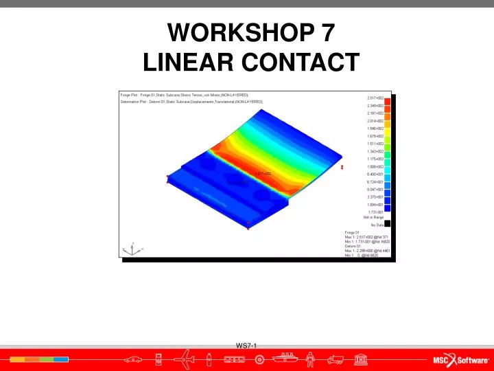
Step 15. Plot Results - Deformation a d Create a Deformation Plot. • Under the Results tab, select Deformation. • Select Results Case Static Subcase. • Select Results Type Displacements, Translational. • Click Update. • The maximum deformation should be 2.3 mm. c b e e
Step 15. Plot Results - Stress Fringe d a c b f Generate a Stress Fringe Plot. • Change the plot type to Fringe. • Change Result type to Stress Tensor. • Select von Mises for Derivation: • Click Update. • The maximum von Mises stress should be 252 MPa. • Click Clear when finished. d e