Download
1 / 45
490 likes | 1.99k Views
Chapter 13 Creep and Superplasticity. Mechanical Behavior of Materials. Creep Strain vs. Time at Constant Temperature. Creep Strain vs. Time at Constant Engineering Stress. Creep Machine. Creep machine with variable lever arms to ensure

E N D
Chapter 13Creep and Superplasticity Mechanical Behavior of Materials
Creep Machine Creep machine with variable lever arms to ensure constant stress on specimen; note that l2 decreases as the length of the specimen increases. (a) Initial position. (b) Length of specimen has increased from L0 to L1.
Larson-Miller Equation Relationship between time to rupture and temperature at three levels of engineering stress, σa, σb, and σc, using Larson–Miller equation (σa > σb > σc).
Larson-Miller Parameter Master plot for Larson–Miller parameter for S-590 alloy (an Fe-based alloy) (C = 17). (From R. M. Goldhoff, Mater.Design Eng., 49 (1959) 93.)
Manson-Haferd Parameter Relationship between time rupture and temperature at three levels of stress, σa, σb, and σc, using Manson–Haferd parameter (σa > σb > σc).
Sherby-Dorn Parameter Relationship between time to rupture and temperature at three levels of stress, σa > σb > σc, using Sherby–Dorn parameter.
Activation Energies for Creep Activation energies for creep (stage II) and self-diffusion for a number of metals. (Adapted with permission from O. D. Sherby and A. K. Miller, J. Eng. Mater. Technol., 101 (1979) 387.)
Secondary Creep Ratio between activation energy for secondary creep and activation energy for bulk diffusion as a function of temperature. (Adapted with permission from O. D. Sherby and A. K. Miller, J. Eng. Mater. Technol., 101 (1979) 387.)
Flow of Vacancies Flow of vacancies according to (a) Nabarro–Herring and (b) Coble mechanisms, resulting in an increase in the length of the specimen.
Dislocation Climb Dislocation climb (a) upwards, under compressive σ22 stresses, and (b) downwards, under tensile σ22 stresses.
Diffusion Creep Different regimes for diffusion creep in alumina; notice that cations (Al3+) and anions (O2−) have different diffusion coefficients, leading to different regimes of dominance. (From A. H. Chokshi and T. G. Langdon, Defect and Diffusion Forum, 66–69 (1989) 1205.)
Dislocations Overcoming Obstacles Dislocation overcoming obstacles by climb, according to Weertman theory. (a) Overcoming Cottrell–Lomer locks. (b) Overcoming an obstacle.
Shear Stress and Shear Strain Rate Shear stress vs. shear strain rate in an aluminum (6061) with 30 vol.% SiC particulate composite in creep. (From K.-T. Park, E. J. Lavernia, and F. A. Mohamed, Acta Met. Mater., 38 (1990) 2149.)
Power Law Power relationship between ˙ε and σ for AISI 316 stainless steel. (Adapted with permission from S. N. Monteiro and T. L. da Silveira, Metalurgia-ABM, 35 (1979) 327.)
Dislocation Glide Effect of stress and temperature on deformation substructure developed in AISI 316 stainless steel in middle of stage II. (Reprinted with permission from H.-J. Kestenbach, W. Krause, and T. L. da Silveira, Acta Met., 26 (1978) 661.)
Grain Boundary Sliding (a) Steady-state grain-boundary sliding with diffusional accommodations. (b) Same process as in (a), in an idealized polycrystal; the dashed lines show the flow of vacancies. (Reprinted with permission from R. Raj and M. F. Ashby, Met. Trans., 2A (1971) 1113.)
Ashby-Verrall’s Model Grain-boundary sliding assisted by diffusion in Ashby–Verrall’s model. (Reprinted with permission from M. F. Ashby and R. A. Verrall, Acta Met., 21 (1973) 149.)
Weertman-Ashby Map for Pure Silver Weertman–Ashby map for pure silver, established for a critical strain rate of 10−8 s−1; it can be seen how the deformation-mechanism fields are affected by the grain size. (Adapted with permission from M. F. Ashby, Acta Met., 20 (1972) 887.)
Weertman-Ashby Map for Tungsten Weertman–Ashby map for tungsten, showing constant strain-rate contours. (Reprinted with permission from M. F. Ashby, Acta Met., 20 (1972) 887.)
Mechanisms of Intergranular Void Nucleation in Creep Mechanisms of intergranular nucleation. (From W. D. Nix and J. C. Gibeling, in Flow and Fracture at ElevatedTemperatures, ed, R. Raj (Metals Park, Ohio: ASM, 1985).)
Heat-Resistant Superalloy: MarM-200 Transmission electron micrograph of Mar M-200; notice the cuboidal γ precipitates. (Courtesy of L. E. Murr.)
Microstructural Strengthening Mechanism in Nickel-based Superalloys (Reprinted with from C. T. Sims and W. C. Hagel, eds., The Superalloys (New York: Wiley, 1972), p. 33.)
Rafting in Ni-Based Superalloys Rafting in MAR M-200 monocrystalline superalloy; (a) original configuration of gamma prime precipitates aligned with three orthogonal cube axes; (b) creep deformed at 1253 K for 28 hours along the [010] direction, leading to coarsening of precipitates along loading direction. (From U. Glatzel, “Microstructure and Internal Strains of Undeformed and Creep Deformed Samples of a Nickel-Based Superalloy,” Habilitation Dissertation,Technische Universit¨at, Berlin, 1994.)
Stress-Strain Curves for Heat Resistant Materials Stress versus temperatures curves for rupture in 1,000 hours for selected nickel-based superalloys. (Reprinted with permission from C. T. Sims and W. C. Hagel, eds., The Superalloys (New York: Wiley, 1972), p. vii.)
Gas Turbine Cross-section of a gas turbine showing different parts. The temperature of gases in combustion chamber reaches 1500 ◦C.
Single-Crystal Turbine Blade (a) Single crystal turbine blade developed for stationary turbine. (Courtesy of U. Glatzel.) (b) Evolution of maximum temperature in gas turbines; notice the significant improvement made possible by the introduction of thermal barrier coatings (TBCs). (Courtesy of V. Thien, Siemens.)
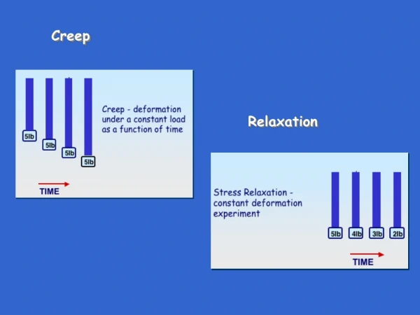
Creep in Polymers Spring–dashpot analogs (a) in series and (b) in parallel.
Maxwell and Voigt Models (a) Strain–time and (b) stress–time predictions for Maxwell and Voigt models.
Viscoelastic Polymer Strain response as a function of time for a glassy, viscoelastic polymer subjected to a constant stress σ0. Increasing the molecular weight or degree of cross-linking tends to promote secondary bonding between chains and thus make the polymer more creep resistant.
Creep Compliances (a) A series of creep compliances vs. time, both on logarithmic scales, over a range of temperature. (b) The individual plots in (a) can be superposed by horizontal shifting (along the log-time axis) by an amount log aT, to obtain a master curve corresponding to a reference temperature Tg of the polymer. (c) Shift along the log-time scale to produce a master curve. (Courtesy of W. Knauss.) (d) “Experimentally” determined shift factor.
Stress Relaxation A constant imposed strain ε0 results in a drop in stress σ(t) as a function of time.
Effect of Crosslinking on Stress Relaxation A master curve obtained in the case of stress relaxation, showing the variation in the reduced modulus as a function of time. Also shown is the effect of cross-linking and molecular weight.
Electromigration Metal interconnect line covered by passivation layer subjected to electromigration; (a) overall scheme; (b) voids and cracks produced by thermal mismatch and electromigration; (c) basic scheme used in Nix–Arzt equation, which assumes grain-boundary diffusion of vacancies counterbalancing electron wind. (Adapted from W. D. Nix and E. Arzt, Met. Trans., 23A (1992) 2007.)
Superplasticity Superplastic tensile deformation in Pb–62% Sn eutectic alloy tested at 415 K and a strain rate of 1.33 × 10⁻⁴ s−1; total strain of 48.5. (From M. M. I. Ahmed and T. G. Langdon, Met. Trans. A, 8 (1977) 1832.)
Plastic Deformation and Superplasticity (a) Schematic representation of plastic deformation in tension with formation and inhibition of necking. (b) Engineering-stress– engineering-strain curves.
Strain-Rate Dependence in Superplastic Region Strain-rate dependence of (a) stress and (b) strain-rate sensitivity for Mg–Al eutectic alloy tested at 350 ◦C (grain size 10 μm). (After D. Lee, Acta. Met., 17 (1969) 1057.)
Tensile Fracture Strain in Superplastic region Tensile fracture strain and stress as a function of strain rate for Zr–22% Al alloy with 2.5-μm grain size. (After F. A. Mohamed, M. M. I. Ahmed, and T. G. Langdon, Met. Trans. A, 8 (1977) 933.)
Effect of Strain Rate Sensitivity on Superplasticity for Different Alloys Effect of strain-rate sensitivity m on maximum tensile elongation for different alloys (Fe, Mg, Pu, Pb–Sr, Ti, Zn, Zr based). (From D. M. R. Taplin, G. L. Dunlop, and T. G. Langdon, Ann. Rev. Mater. Sci., 9 (1979) 151.)
Cavitation in Superplasticity Cavitation in superplasticity formed 7475-T6 aluminum alloy (ε = 3.5) at 475 ◦C and 5 × 10⁻⁴ s−1. (a) Atmospheric pressure. (b) Hydrostatic pressure P = 4 MPa. (Courtesy of A. K. Mukherjee.)
Effect of Grain Size on Elongation (a) Effect of grain size on elongation: (A) Initial configuration. (B) Large grains. (C) Fine grains (10 μm) (Reprinted with permission from N. E. Paton, C. H. Hamilton, J. Wert, and M. Mahoney, J. Metal, 34 (1981) No. 8, 21.) (b) Failure strains increase with superimposed hydrostatic pressure (from 0 to 5.6 MPa). (Courtesy of A. K. Mukherjee.)