Download

1 / 44
440 likes | 444 Views
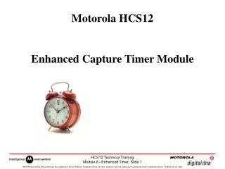
Motorola HCS12 Enhanced Capture Timer Module. 8-channel ECT implemented on all HCS12 ‘A’ family parts. ‘A’ family almost identical to ‘D’ family (no CAN/no J1850 on ‘A’). HCS12 CPU. 32KB -> 512KB FLASH options. 2KB->14KB RAM. 1KB->4KB EEPROM. ATD1 10 bit, 16ch. ATD0 10-bit, 8 ch.

E N D
8-channel ECT implemented on all HCS12 ‘A’ family parts. ‘A’ family almost identical to ‘D’ family (no CAN/no J1850 on ‘A’). HCS12 CPU 32KB -> 512KB FLASH options 2KB->14KB RAM 1KB->4KB EEPROM ATD1 10 bit, 16ch. ATD0 10-bit, 8 ch ATD1 10-bit, 8 ch IIC 2 x SCI Up to 3 x SPI Enhanced Capture Timer 16-bit, 8 ch Internal Bus 5v operating voltage PWM 8-bit 8 ch / 16-bit 4 ch 16key Wakeup IRQ Ports HCS12 “A” Family
ECT Hardware Overview • One 16-bit master up-counter with programmable prescaler. • One 16-bit modulus down-counter, again with programmable prescaler. • Eight independent timer channels, each capable of input capture and output compare functions. • Four 8-bit pulse accumulators which may alternatively be configured as two 16-bit pulse accumulators. • A number of programmable registers to provide detailed configuration of device function.
Features • Upwards comparable with MC68HC12 timer. • Modular design permits future expansion. • 0 to 8 Input Capture channels. • - 16-Bit Buffer Register for four Input Capture (IC) channels. • 0 to 8 Output Compare channels. • Four 8-Bit Pulse Accumulators with 8-bit buffer registers • associated with the four buffered IC channels. • Configurable also as two 16-Bit Pulse Accumulators. • . • Unique exception vector for • each timer channel. • • 16-Bit Modulus Down-Counter with 4-bit Prescaler. • • Four user selectable Delay Counters for input noise • immunity increase. SCI 1 SCI 1 ATD 1 ATD 0 12K SRAM 256K FLASEEPROM Internal Bus SPI 2 or PWM CH 4-7 SPI 1 or PWM CH 0-3 SPI 0 BKP INT MMI PWM 8 CHAN HCS12 CPU SIM CM BDM MEBI PIM PLL PIT msCAN 4 or IIC msCAN 3 msCAN 2 msCAN 1 BDLC or msCAN 0 ECT 8 CHAN 4K BYTES EEPROM
TOF ******* ****** ** **** $0000 $FFFF $FFFE TIMER STRUCTURE PRE-SCALER PR[2:0] M Clock 1 2 4 8 16 32 64 128 TCNT CLK 15...........................................0 Address Offset $0004, 05 . TCNT B0.......……...B7 B8……..........B15 TEN PIN DATA BUS PA PULSE Accumulator TSCR1 - TIMER SYSTEM CONTROL REGISTER R R R R TEN TSWAI TSFRZ TFFCA $0006 RST: 0 0 0 0 0 0 0 0 R = Reserved 1 -CLOCKS COUNTER ENABLE 0 - CLOCKS COUNTER DISABLE
SELECTION PRESCALER Timer, Prescaler and Counter REGISTERS: 16 BIT FREE RUNNING /MODULO COUNTER B15............................................................................................................................…B0 Address Offset $0004, $0005 1. TCNT RST: 0........................................................................................................................0 B7......................................................................B0 $000F TOF 0 0 0 0 0 0 0 2. TFLG2 RST: 0 0 0 0 0 0 0 0 Timer Overflow Flag Write a ‘1’ to clear B7....................................................................................B0 TOI 0 0 0 TCRE PR2 PR1 PR0 3. TSCR2 $000D PR2 PR1 PR0 DIVIDE BY RST: 0 0 0 0 0 0 0 0 0 0 0 0 1 1 1 1 0 0 1 1 0 0 1 1 0 1 0 1 0 1 0 1 1 2 4 8 16 32 64 128 1 - TIMER RESET BY OC7 MATCH 0 - COUNTER IS FREE RUNING 1 - TIMER OVERFLOW INTERRUPT ENABLE 0 - TIMER OVERFLOW INTERRUPT DISABLE TCRE - ALLOWS FOR PULSE WIDTH MODULATION FUNCTION. * RESERVED
TIMER OPERATION USEFUL FOR: 1. BASIS FOR ALL THE TIMING FUNCTIONS 2. PROVIDING TIME INFORMATION TO PROGRAMS DESCRIPTION: THE E-CLOCK DRIVES A PRESCALER, DIVISIBLE BY 1, AND UP T0 128, WHICH IN TURN DRIVES A 16 BIT COUNTER. WHEN THE TIMER GOES FROM $FFFF TO $0000: • - THE TIMER OVERFLOW FLAG BIT IS SET • IN ADDITION: - AN OVERFLOW INTERRUPT MAY OCCUR
Timer Overflow Interrupt INTERRUPT: FOR TIMER OVERFLOW • TO CLEAR INTERRUPT WRITE 1 TO TOF BIT TFLG2. DO NOT USE BIT MANIPULATION INSTRUCTIONS (SINCE RM/W OPERATION). • TIMER OVERFLOW VECTOR USED. RESET CONDITIONS: TCNT IS INITIALIZED TO ALL ZEROES AND Disabled TIMER OVERFLOW INTERRUPTS ARE Disabled TC7 - TC0 REGISTERS ARE CLEARED TIMER OVERFLOW FLAG IS CLEARED PRESCALER IS 1
Toggle Pin Set Pin Clear Pin COMPARE OR OR PERFORM ACTION Output Compare Function • Provides a mechanism to output a signal at a specific time TCNT Action taken upon match of compare register with counter Compare/Capture Unit 16-Bit Free-Running Counter MATCH! Pin OCx Pin Control Logic Comparator TOCx 16-Bit Output Compare Register (programmed by software) Status Flag is set upon compare match OCxF Optional Local Interrupt Mask (Enabled through software) Interrupt Request to CPU OCxI • UP TO 8 separate Output Compare Functions • Each Output Compare Function has its own Vector and Controls
Output Compare, OC7-OC0 (1 of 4) 1. OUTPUT WAVEFORM CONTROL (SOFTWARE CONTROLLED) USEFUL FOR: 2. ELAPSED TIME INDICATOR (TO EXTERNAL CIRCUITRY) DESCRIPTION: DURING EACH E-CLOCK CYCLE, THE OUTPUT COMPARE REGISTERS ARE COMPARED TO THE FREE-RUNNING COUNTER. IF THERE IS A COMPARE THEN: 1. THE INTERRUPT FLAG BIT IS SET IN ADDITION, EITHER OR BOTH OF THE FOLLOWING MAY OCCUR: 1. THE STATE OF THE ASSOCIATED OUTPUT PIN MAY BE CHANGED 2. AN INTERRUPT IS GENERATED TO CPU, IF Enabled
16 BIT CAPTURE COMPARE REGISTER (TC7) 16 BIT CAPTURE COMPARE REGISTER (TC0) B7 B6 B5 B4 B3 B2 B1 B0 B7 B6 B5 B4 B3 B2 B1 B0 B7 B6 B5 B4 B3 B2 B1 B0 OMX OLX Action on OCx B7 B6 B5 B4 B3 B2 B1 B0 0 0 No Action OCx 0 1 Toggle OCx 1 0 Drive OCx LO 1 1 Drive OCx HI Output Compare(2 of 4) REGISTERS: Address Offset $0010 - $0011 - - $001E - $001F - - 1. TC7 – TC0 $000E C7F C6F C5F C4F C3F C2F C1F C0F 2. TFLG1 COMPARE/CAPTURE FLAGS Write ‘1’ to Clear Interrupt Flag RST: 0 0 0 0 0 0 0 0 $000C C7I C6I C5I C4I C3I C2I C1I C0I 3. TIE COMPARE/ CAPTURE MASK 0 = Interrupt Request Masked 1 = Interrupt Request Enabled RST: 0 0 0 0 0 0 0 0 $0008 OM7 OL7 OM6 OL6 OM5 OL5 OM4 OL4 4. TCTL1 OUTPUT MODE AND RST: 0 0 0 0 0 0 0 0 OUTPUT LEVEL (O7–OC0) $0009 OM3 OL3 OM2 OL2 OM1 OL1 OM0 OL0 5. TCTL2 RST: 0 0 0 0 0 0 0 0
Force Output Compare (3 of 4) - FORCE OUTPUT COMPARE 5. CFORC B7 B6 B5 B4 B3 B2 B1 B0 $0001 FOC7 FOC6 FOC5 FOC4 FOC3 FOC2 FOC1 FOC0 RST: 0 0 0 0 0 0 0 0 PINS: 1. OC7–OC0 (PORT T PINS 7-0) USED TO STABLISH INITIAL TIMER PIN STATES. NOTE: FORCE OUTPUT COMPARE DOES NOT SET OCx FLAGS. FORCE OUTPUT COMPARE 7 MAY AFFECT ANY OR ALL OUTPUT COMPARE PINS.
• OUTPUT COMPARE REGISTERS ARE INITIALIZED TO $0000 • OUTPUT COMPARE PINS ARE DISCONNECTED FROM OUTPUT COMPARE FUNCTIONS • INTERRUPTS are Disabled • FLAG BITS ARE CLEARED • FORCE COMPARE BITS ARE CLEARED Output Compare, OC7-OC0 (4 of 4) INTERRUPTS: FOR OUTPUT COMPARES OC7–OC0 • TO CLEAR INTERRUPT, WRITE 1 TO OCxF BIT IN TFLG1 DO NOT USE BIT MANIPULATION INSTRUCTIONS (SINCE RM/W OPERATION) • OC7–OC0 VECTORS ARE USED RESET CONDITIONS: • FREE RUNNING COUNTER (TCNT) INITIALIZED TO $0000 AND Disabled.
Output Compare, OC7 (1 of 2) USEFUL FOR: 1. CONTROL OF MULTIPLE OUTPUT COMPARE PINS 2. CONTROL OF A SINGLE PIN BY TWO OUTPUT COMPARES (THUS, SHORT PULSES ARE POSSIBLE). DESCRIPTION: DURING EACH E-CLOCK CYCLE, THE OUTPUT COMPARE REGISTER 1 IS COMPARED TO THE FREE-RUNNING COUNTER. IF THERE IS A COMPARE THEN: 1. THE INTERRUPT FLAG BIT IS SET IN ADDITION, EITHER OR BOTH OF THE FOLLOWING MAY OCCUR: 1. THE STATE OF OUTPUT PINS OC7–OC0 MAY BE CHANGED 2. AN INTERRUPT MAY OCCUR • OC7 CAN AFFECT MULTIPLE PINS (OC7–OC0) • OC7 ACTION OVERRIDES ANY CONFLICTING OC7–OC0 ACTION FOR A GIVEN PIN.
Output Compare 7 (2 of 2) 1 - TC7 -16 BIT COMPARE REGISTER 7. 2. TCNT - 16-BIT TIMER B15...............................................................................................................................................................B0 $0004, $05 RST: 0..................................................................................................................................................0 3. TFLG1 - TIMER FLAG1 B7.............................................................................................B0 $000E C7F C6F C5F C4F C3F C2F C1F C0F RST: 0 0 0 0 0 0 0 0 4. TIE - TIMER INTERRUPT ENABLE B7.............................................................................................B0 $000C C7I C6F C5F C4F C3F C2F C1F C0F RST: 0 0 0 0 0 0 0 0 5. OC7M - OC7MASK B7.............................................................................................B0 $0002 OC7M7 OC7M6 OC7M5 OC7M4 OC7M3 OC7M2 OC7M1 OC7M0 RST: 0 0 0 0 0 0 0 0 B7.............................................................................................B0 6. OC7D - OC7DATA $0003 OC7D7 OC7D6 OC7D5 OC7D4 OC7D3 OC7D2 OC7D1 OC7D0 RST: 0 0 0 0 0 0 0 0
Output Compare 7 Flow Chart WRITE BIT TO FOC7 1ST COUNTER E CYCLE Y AND OUTPUT Y FOR THIS SET START COMPARE REG COUNTER OC7F MATCH VALUE ? ? N N N OC7I=1? Y END ASSERT INTERRUPT OC7M0 OC7D0 OC7M7 OC7D7 0 0 0 0 DRIVE OC0 0 1 DRIVE OC7 0 1 • • • • • PIN LOW PIN LOW 1 0 1 0 1 1 1 1 DRIVE OC0 DRIVE OC7 PIN HIGH PIN HIGH
DISCONNECT OMx OLx 0 0 0 1 1 0 1 1 Output Compare Flow Chart (Complete) WRITE BIT TO FOCx 1ST E CYCLE COUNTER Y FOR THIS Y AND OUTPUT SET START COUNTER COMPARE REG OCxF VALUE MATCH ? ? N N N OCxI=1? n Y OC7 ASSERTED END ASSERT THIS E INTERRUPT N CYCLE ? Y TOGGLE OC7Mx OC7Dx OCx PIN 0 0 DRIVE OCx 0 1 DRIVE OCx PIN LOW 1 0 PIN LOW 1 1 DRIVE OCx DRIVE OCx PIN HIGH PIN HIGH • FOR OCx = OC7 – OC0
Timer Toggle on Overflow TTOV -Timer Toggle On Overflow Register Address Offset $0007 TOV7 TOV6 TOV5 TOV4 TOV3 TOV2 TOV1 TOV0 RST: 0……………………………………………………………….…..0 TOVx - TOGGLE ON TIMER OVERFLOW TOVx Toggles output compare pin on overflow. This feature is applicable only when channel is configured for Output Compare Function.
Timer Output Compare Exercise ; Timer lab - outputs 1 to 8 channels of PWM out of Port T org $4000 main: ; use all channels as output compare function ; disable timer, operate in wait, continue in BDM ; fast clear enables ; enable clear of OCn when match on all channels ; disable Interrupts ; disable pull-ups, normal drive, TCNT reset by OC7 ; set prescaler to divide-by-4 ; set the OC7 to be an output port ; enable OC7 to set the output compare pins to high ; OC7 is the period of the PWM ; OC0 is high for 32 clocks ; OC1 is high for 64 clocks ; OC2 is high for 128 clocks ; OC3 is high for 256 clocks ; OC4 is high for 512 clocks ; OC5 is high for 1024 clocks ; OC6 is high for 2048 clocks ; ready to go, now enable the timer loop: ; wait here
16-bit Holding Register Input Capture Function • Provides a mechanism to capture the time at which an external event occurs TCNT Compare/Capture Unit 16-bit Free Running Counter Rising Edges Falling Edges Any Edge Inhibit OR OR TICx Edge Delay Counter Pin ICx 16-bit Input Capture Latch Edge Select & Detect ICxF Status Flag is set upon capture Interrupt Request to CPU Optional Local Interrupt Mask (Enabled through software) ICxI DLYCT - Delay Counter Control Register • Up to 8 separate Input Capture function, IC7 - IC0 • Each Input Capture Function has its own Vector and Controls Bit 7 6 5 4 3 2 1 0 Address Offset $0029 0 0 0 0 0 0 DLY1 DLY0 DLY[1:0] - Delay Counter Values 00 = Disabled 01 = 256 M Clocks 10 = 512 M Clocks 11 = 1024 M Clocks Note: Delay Counter produces a Pulse at preset clock count if the level of the input signal is the opposite of the level before the transition. • Examples: ABS braking. Radar distance • measurement. Heart rate monitoring.
Input Capture, IC7-IC0(1 of 3) USEFUL FOR: 1. MEASURING TIME BETWEEN EVENTS (OCCURING IN HARDWARE) 2. REACTING TO REAL–TIME EVENTS DESCRIPTION: INPUT CAPTURE EDGE DETECTORS SENSE WHEN AN EDGE OCCURS ON THE PIN. IF AN EDGE OCCURS, THE FOLLOWING MAY HAPPEN: • THE COUNTER VALUE GOES INTO THE INPUT • CAPTURE REGISTER; A STATUS FLAG IS SET. • 2. AN INTERRUPT IS GENERATED TO CPU, IF Enabled.
16 BIT CAPTURE COMPARE REGISTER (TC0) 16 BIT CAPTURE COMPARE REGISTER (TC7) B7 B6 B5 B4 B3 B2 B1 B0 B7 B6 B5 B4 B3 B2 B1 B0 B7 B6 B5 B4 B3 B2 B1 B0 Input Capture Edge Control (IC7–IC0) EDGxB EDGxA ICx EDGE 0 0 No Edge – ICx Disabled 0 1 Rising Edges Only B7 B6 B5 B4 B3 B2 B1 B0 1 0 Falling Edges Only 1 1 Any Edge Input Capture, IC7-IC0 (2 of 3) Address Offset $0010 - $0011 - - $001E - $001F 1. TC7 – TC0 - - $000E C7F C6F C5F C4F C3F C2F C1F C0F B2 B1 B0 2. TFLG1 COMPARE/CAPTURE FLAGS Write ‘1’ to Clear Interrupt Flag RST: 0 0 0 0 0 0 0 0 $000C C7I C6I C5I C4I C3I C2I C1I C0I 3. TMSK1 COMPARE/ CAPTURE MASK 0 = Interrupt Request Masked 1 = Interrupt Request Enabled RST: 0 0 0 0 0 0 0 0 $000A EDG7B EDG7A EDG6B EDG6A EDG5B EDG5A EDG4B EDG4A 4. TCTL3 RST: 0 0 0 0 0 0 0 0 $000B EDG3B EDG3A EDG2B EDG2A EDG1B EDG1A EDG0B EDG0A 5. TCTL4 RST: 0 0 0 0 0 0 0 0
Input Capture, IC7-IC0 (3 of 3) INTERRUPTS: FOR INPUT CAPTURES IC7 – IC0 • TO CLEAR INTERRUPT, WRITE 1 TO ICxF BIT IN TFLG1 DO NOT USE BIT MANIPULATION INSTRUCTIONS (SINCE RM/W OPERATION) • IC7–IC0 VECTORS ARE USED. RESET CONDITIONS: • INPUT CAPTURE FUNCTIONS ARE DISCONNECTED FROM INPUT CAPTURE PINS • INTERRUPTS ARE DISABLED • FLAG BITS ARE CLEARED
Input Capture Flow Chart EDGE IS START DETECTED EDGxB EDGxA END 0 0 N RISING 0 1 EDGE? 1 0 1 1 Y N FALLING ASSERT EDGE? INTERRUPT Y N Y PUT TIMER ICxI=1? VALUE IN TICx; SET FLAG,ICxF
B7 B6 B5 B4 B3 B2 B1 B0 IC/OC Select TIOS -TIMER INPUT CAPTURE/OUTPUT COMPARE SELECT REGISTER $0000 IOS7 IOS6 IOS5 IOS4 IOS3 IOS2 IOS1 IOS0 RST: 0 0 0 0 0 0 0 0 IOSx = 1 SELECT OC FUNCTION = 0 SELECT IC FUNCTION TSCR - TIMER SYSTEM CONTROL REGISTER TEN TSWAI TSFRZ TFFCA Reserved $0006 RST: 0……………………………………………………………………………0 TFFCA - TIMER FAST FLAG CLEAR ENABLE 0 = TIMER FLAG CLEARING NORMALLY 1 = A READ FOR IC, A WRITE OF OC REGISTER CAUSES CORRESPONDING CHANNEL FLAG TO CLEAR TSBCK - TIMER STOP IN DEBUG MODE 0 = DO NOT STOP 1 = DISABLE TIMER IN DEBUG MODE TSWAI - TIMER STOP IN WAIT 0 = NORMAL OPERATION 1 = DISABLE TIMER IN WAIT MODE TIMER ENABLE 1 -CLOCKS COUNTER ENABLE 0 - CLOCKS COUNTER DISABLE
Timer Input Capture Lab Write a routine to measure the period of a square wave on TC1. The routine uses the Input Capture to measure the period from one rising edge to the next. Use software polling routine, non-Interrupt-driven. Assume system clock is 25MHZ, set the Timer prescaler to divide by 4. • TIME1 EQU $1200 ADDRESS OF TIME1 • DIFF EQU $1202 ADDRESS OF DIFFERENCE • ORG $4000 PROGRAM BEGINS HERE 1. Load X register with register block address 2. Configure channel 1 for input capture (write TIOS) 3. Set TCTL4 to capture rising edge on channel 1. 4. Disable Ch1 Interrupts in TMSK2 5. Enable and start timer 6. Read Timer status register into Accumulator 7. Clear Timer Ch1 status flag C1F. 8. Wait here until C1F is set, else go to 9. 9. Load captured value into Accumulator D. 10. Store D to Ram in TIME1 11. Clear C1F by writing a 1 to it 12. Wait here until C1F is set, else go to 13. 13. Load captured value into Accumulator D. 14. Subtract TIME1 from D 15. Store D to Ram in DIFF location. 16. Return from subroutine
Pulse Accumulator USEFUL FOR: 1. EVENT COUNTING 2. GATED TIME ACCUMULATION DESCRIPTION: IF PULSE ACCUMULATION IS Enabled, THEN HCS12 RESPONDS TO EDGES ON PAI BY INCREMENTING THE 8 OR 16-BIT PULSE Accumulator COUNTER. EVENT COUNTING MODE: INPUT EDGES ON PAI INCREMENT THE 8/16-BIT COUNTER GATED TIME ACCUMULATION MODE: THE 8/16-BIT COUNTER IS INCREMENTED BY AN E/64 CLOCK IF Enabled BY THE LAST EDGE ON PAI IF THE SPECIFIED EDGE OCCURS, THEN: 1. THE PULSE Accumulator FLAG BIT IS SET IN ADDITION, THE FOLLOWING MAY OCCUR: 1. THE COUNTER MAY BE INCREMENTED 2. THE PULSE Accumulator OVERFLOW BIT MAY SET 3. AN INTERRUPT IS GENERATED TO CPU, IF Enabled.
Event Counter Mode Pulse accumulator is an event counter. An event is a prescribed external pulse applied to the relative MCU pin. Each pulse increments the value of the pulse accumulator register. Trigger event can be configured as a rising or a falling edge. Gated Accumulation Mode Pulse accumulator is an event lengthcounter. Counter records the length of a pulse applied on the relative MCU pin. The MCU internal bus clock is divided by 64 and applied to the pulse accumulator for the duration of the external event. Trigger event is configurable as a logic high event or a logic low event. ECLK/64 Pulse Accumulator +1 COUNT! EVENT PULSE ECLK/64
Pulse Accumulator Block Diagram TCx PIN Logic Delay Counter PTx D A T A B U S POLARITY CONTROL Edge Detector PIN + 8/16 BIT CNTR SELECTED CLOCK IRQ DIV by 64 LATCH Control Reg. DLYCT - Delay Counter Control Register Address Offset $0029 Bit 7 6 5 4 3 2 1 0 Note 1: PTx may be used as Pulse Accumulator, Input Capture or Output Compare pin. Where PTx = PT0 - PT3 0 0 0 0 0 0 DLY1 DLY0 DLY[1:0] - Delay Counter Values 00 = Disabled 01 = 256 M Clocks 10 = 512 M Clocks 11 = 1024 M Clocks Note 2: Delay Counter produces a Pulse at preset clock count if the level of the input signal is the opposite of the level before the transition.
PA Registers (1 of 2) Address Offset $0022 $0023 $0024 $0025 $0028 $0032 $0033 $0034 $0035 Pulse Accumulator Count Registers PACN3 PACN2 PACN1 PACN0 ICPAR - Input Control pulse Accumulator Register PAxEN - PAx Enable Pulse Accumulator Holding Registers PA3H PA2H PA1H PA0H PAxH - Used to latch PAx when enabled PA3H - PA0H Registers are read only
PA Registers (2 of 2) PACTL - PA Control Register Address Offset $0020 PAI - PA Input Interrupt Enable 1 = PAI Interrupt Enabled 0 = PAI Interrupt Disabled PAEN - PA Enable 1 = Pulse Accumulator Enabled 0 = Pulse Accumulator Disabled PAOVI - PA Overflow Interrupt Enable 1 = PAO Interrupt Enabled 0 = PAO Interrupt Disabled Clock Selection Pin Action PAFLG - PA Interrupt Flag Register Address Offset $0021 PAOVF -- Pulse Accumulator Overflow Flag PAIF - Pulse Accumulator Input Flag Sets when PA overflows from $FF to $00 Sets when the programmed transition is detected on PA Pin.
Pulse Accumulator Interrupts: For Pulse Accumulator Input and Pulse Accumulator Overflow. • To clear Interrupt write a ‘1’ to PAIF or PAOVF bits in TFLG2. Do not use bit manipulation instructions (since RM/W operation). • Pulse Accumulator or Pulse Accumulator Overflow vector used Reset conditions: - Pulse accumulator is disabled - Event counter mode - Falling edges(event counter mode) or PAI high enables (gated time accumulation mode) - Interrupts are disabled - Flag bits are cleared
• For event counting mode, PEDGE selects which PAI edge is used to increment the PACNT register. • For gated accumulation mode, PEDGE selects which PAI state is used to inhibit counting. (i.e. PEDGE = 1 inhibit counting when PAI = HI). Since gated accumulation mode will only increment PACNT every 64 E clocks, waveforms with gated times less than 64 E clocks are not guaranteed to be detected. • The measured gated time of any waveform is only accurate to within 64 E clocks for each counting state on the PAI pin. • Pulse Accumulator Modes
ECT Latch Mode Latch Mode: LATQ = 1 Modulus Down-Counter causes IC x & PA x registers to transfer to their corresponding holding registers when Counter reaches $0000, or when Down-Counter is written with $0000.. In this mode, IC registers are transferred to their holding register when ICLAT bit is written in the MCCTL register
TIMCLK M Clock PT0 PT1 PT2 PT3 PT4 PT5 PT6 PT7 SH37 ECT Queue Mode Queue Mode: LATQ = 0 An Input Capture x Event causes the IC register to transfer to corresponding Holding register x, and new captured value is written to corresponding IC register. This mode also causes the PA x to transfer to it’s corresponding holding register when IC holding register x is read. Modulus Down-Counter in this mode may only be used to generate periodic Interrupts.
Modulus Down-Counter COUNT DOWN TO ZERO • Binary down-counter. Full control over count start value. • Applications in accurate event timing - used to generate periodic flags and interrupts. • Runs independently of master timer. Clocked directly from the bus clock through a dedicated prescaler. • Can be set to generate flags /interrupts at a discrete time from activation, or set to reload the count start value upon reaching $0000 (periodic modulus mode). LOAD PERFORM ACTION
PROCESS INTERRUPT SET UP INTERRUPT RUN ECT Interrupt Generation • ECT has thirteen discrete interrupt vectors - No need to continually poll critical status flags. • Interrupts allow delegation and optimisation of core use. • Extremely flexible. Examples of interrupt usage: • Launch routines at real-time fixed intervals. • Perform real-time period measurement. • Counting of high-frequency events. CORE UNUSED BY ECT
Features on ECT module in addition to standard TIM module :- 16-bit buffer registers on four input capture channels. Four 8-bit / two 16-bit pulse accumulators. 16-bit modulus down-counter with 4-bit prescaler. Four user selectable delay counters for increased noise immunity. Main timer prescaler extended to 7-bit. EXTERNAL EVENT EXTERNAL EVENT READ DATA COPY COPY COPY READ DATA Enhanced Capture Master Timer Input Capture Register Holding Register
Modulus Counter Registers MCCNT - Modulus Down-Counter Count Register Address Offset $0036, 37 Modulus Down-Counter may be used to generate periodic Interrupts. It can also be used to latch IC and PA registers to their holding registers. MCCTL - Modulus Down-Counter Control Register Address Offset $0026 MCZI - Modulus Counter Interrupt Enable MODMC - Modulus Mode Enable 1 = Counter is loaded with last value written to Modulus Count Register. 0 = Counter counts once from value written to it and will stop at $0000. RDMCL - Read Modulus Down Counter Load 1 = Reads of Counter returns the contents of the Load Register. 0 = Read of Counter returns current value of the present count. ICLAT - Input Capture Force Latch Action When Latch Mode is enabled, write ‘1’ to this bit causes IC3-IC0 and their corresponding Pulse Accumulators to be latched into their associate holding registers. FLMC - Force Load Register into Modulus Counter by writing ‘1’ to this bit MCEN - Modulus Down-Counter Enable 1 = Modulus Counter Enabled. 0 = Modulus Counter Disabled. MCPR[1:0] - Modulus Counter Prescaler Select 00 = Div/1 01 = Div/4 10 = Div/8 11 = Div/16 MCFLG - Modulus Down-Counter Flag Register Address Offset $0027 POLF{3:0] - First Input Capture Polarity Status 1 = Input Capture x was caused by rising edge. 0 = Input Capture x was caused by falling edge. Where x = IC3 - IC0. MCZF - Modulus Counter Underflow Interrupt Flag. This Flag is set when Modulus Counter reaches $0000. Write ‘1’ to clear.
ECT Control Registers ICSYS - Input Control System Register Address Offset $002B SHxy — Share Input action of Input Capture Channels x and y 1 = The channel input ‘x’ causes the same action on the channel ‘y’. The port pin ‘x’ and the corresponding edge detector is used to be active on the channel ‘y’. 0 = Normal operation TFMOD — Timer Flag-setting Mode Allows a timer Interrupt to be generated after capturing two values in the capture and holding registers instead of generating an Interrupt for every capture. 1 = If in Queue mode, timer flags C3F-C0F are set when a latch on the corresponding holding register occurs. 0 = C3F -C0F are when a valid edge occurs on corresponding IC timer pin. PACMX - 8-Bit pulse Accumulator Max Count 1 = When PA reaches the value $FF, it will not increment further. 0 = PA will overflow to $00. Note: For PACMX = 1, when count is read as $FF, it indicate a count of 255 or more. BUFEN -IC Buffer Enable 1 = IC & PA Holding Registers are enabled. 0 = IC & PA Holding Registers are disabled. LATQ = Input Control Latch or Queue Mode Enable 1 = Latch mode is enabled. 0 = Queue Mode is enabled. ICOVW - Input Control Overwrite Register Address Offset $002A NOVWx - No Input Capture Overwrite These control bits prevent an overwrite to the IC x registers until read or latched in the holding register 1 = The related IC or Holding register will not be overwritten unless read or latched. 0 = The related Capture register will be overwritten when a new input capture or latch occurs.
Adjust Pressure to LF Wheel ABS Application Example If LF Wheel Measured Period > RF Wheel Measured Period, Then PT0 LF WHEEL RF WHEEL LR WHEEL RR WHEEL SENSOR 1 SIGNAL CONDITIONING LOGIC IC/PA H C S 1 2 SENSOR 2 PT1 SIGNAL CONDITIONING LOGIC IC/PA SENSOR 3 PT2 SIGNAL CONDITIONING LOGIC IC/PA Any port pins may be used to switch brake fluid pumps on and off. SENSOR 4 PT3 SIGNAL CONDITIONING LOGIC IC/PA TIMER PB1 BRAKE FLUID PB2 PUMP PB3 SYSTEM PB4 • Timer Input Captures measure wheel rotation. • Send commands to brake fluid pumps to adjust pressure.
FLYWHEEL Angle Based Engine ControlApplication Example PIN SENSOR SENSOR INPUT CAPTURE SIGNAL CONDITIONING LOGIC H C S 1 2 T I M E R CAMSHAFT PIN INPUT CAPTURE SIGNAL CONDITIONING LOGIC PIN SPARK PLUG SPARK PLUG FUEL INJECTOR FUEL INJECTOR OUTPUT COMPARE SIGNAL CONDITIONING LOGIC PIN OUTPUT COMPARE SIGNAL CONDITIONING LOGIC PIN OUTPUT COMPARE SIGNAL CONDITIONING LOGIC PIN OUTPUT COMPARE SIGNAL CONDITIONING LOGIC
CONCLUSIONTIMER FUNCTIONS Timer Output Compare Input Capture Pulse Accumulator Latch & Queue Modes