Download
1 / 28
280 likes | 356 Views
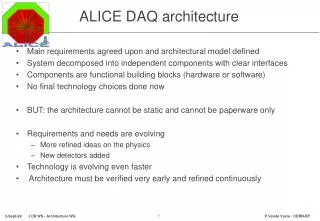
Simulating the ALICE DAQ/trigger/HLT. Tome Anti č i ć Rudjer Boskovic Institute. LHC DAYS IN SPLIT 2004. Peri- pheral. Central. Semi-central. PE SC CE. Want to accept all rare decays. A problem has to happen…. Detectors. ~50 GByte/sec

E N D
Simulating the ALICE DAQ/trigger/HLT Tome Antičić Rudjer Boskovic Institute LHC DAYS IN SPLIT 2004
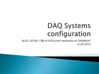
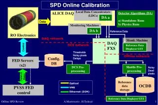
Peri- pheral Central Semi-central PE SC CE Want to accept all rare decays A problem has to happen… Detectors ~50 GByte/sec (after Past/Future considerations,time to read events into detector buffers,zero suppression) CE,SC,PE EL MU Front end electronics ~25 GByte/sec DAQ ~1.25 GB/sec PDS • Of course ALICE will loose most of interesting (Electron –EL , and Muon -MU) events. • But, need to be able to quantify this before start to successfully design DAQ/Trigger/HLT to recover the EL and MU events
CE, SC,PE, EL (+- 88 msec) MU (+- 7 msec) ~25% for 8000 Hz What are we dealing with in ALICE? • Event sizes per detector per trigger type Mbyte • Different triggers involve different detector sets TPC TRD Drift Pixel Muon HMPID CPV TPC property • Past/future protection T= -88 msec T= 0 msec T= 88 msec TIME fraction accepted = e-2*P/F_time*InteractionRate
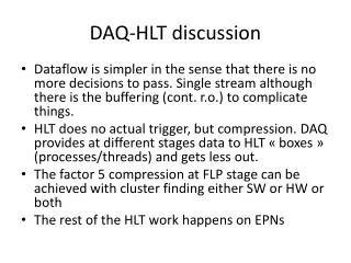
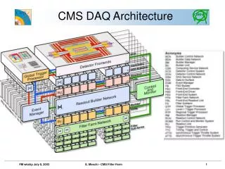
Muon Trg detectors Inner tracking system TPC TRD Particle identifcation Multi Event buff Trg data RORC RORC RORC RORC RORC RORC RORC RORC RORC RORC RORC RORC L0 LDC LDC LDC LDC LDC LDC L1 L2 Gigabit SWITCH 40 Mb/sec GDC GDC GDC GDC SWITCH PDS PDS PDS PDS ALICE DAQ/Trigger/HLT (What is simulated) 216 DDL 1oo Mb/s 216 1oo Mb/s 216 HLT farm EDM Trigger system rejects 80% of EL
ALICE detector readout electronics model L0 SEB L0 MEB L2 SEB L2 MEB L1 SEB L1 MEB RORC DET L0-DL L2-DL L1-DL F2D-DL L0 SEB L0 MEB L2 SEB L2 MEB L1 SEB L1 MEB RORC • SEB- single event buffer • MEB-multi event buffer • DL-transmission delay L0-DL L2-DL L1-DL F2D-DL
Muon Trg detectors Inner tracking system TPC TRD Particle identifcation Multi Event buff Trg data RORC RORC RORC RORC RORC RORC RORC RORC RORC RORC RORC RORC L0 LDC LDC LDC LDC LDC LDC L1 L2 Gigabit SWITCH 40 Mb/sec GDC GDC GDC GDC x 40 SWITCH PDS PDS PDS PDS ALICE DAQ/Trigger/HLT (What is simulated) 216 DDL 1oo Mb/s 216 1oo Mb/s 216 HLT farm EDM Trigger system rejects 80% of EL
L2 rates Results:As expected,we have a problem Detectors CE,SC,PE EL MU Front end electronics ~25 GByte/sec (limited by DDL rates) DAQ ~1.25 GB/sec PDS Simulation shows a huge reduction of the original rare decays (Electron-EL and Muon-MU) due to various backpressures,caused by central-CE semicentral –SC, and peripheral-PE blocking the event buffers in detectors
L1 CE/SC/PE The proposed solution • High/low level at LDC to inform the Trigger to block “non important” high bandwidth triggers ( CE, SC, PE) to prevent multi-event buffer getting full At high levelanyLDC buffer for any detector blocks CE,SC,PE CE,SC,PE restarted when all LDCs fall below low level CTP Rare event handler high L1 CE/SC/PE low all LDCs • Downscaling (when a fraction of a trigger type is outright rejected) is designed in the Trigger, so can use • use to prevent excessive CE, SC, PE fraction during on times • cannot on its own solve problem as extremely sensitive (simulation showed!) on exact running conditions ? Will this mechanism work? ? If so, will it require new hardware, or will a software solution work?
Excellent, stable behavior! Pb-Pb results • LDC high/low control, downscaling by 0.2 of PE,SC and CE events L2 rates Fraction of time detector busy
Pb-Pb results with different running conditions • Very high percentage of max rate (i.e. only P/F considerations: n/N = e-2*P/F*Rate) ) accepted for both electron and muon events for all reasonable running/physics conditions • No backpressure rate limitation,detectors not busy • Further study showed delays for LDC high/low feedback of several 100 msec do not degrade behavior • software solution allowed 16000 Hz 3200 Hz EL,MU 4000 Hz 800 Hz EL,MU 8000 Hz 800 Hz EL,MU 8000 Hz 1600 Hz EL,MU
Trigger Feedback part of DAQ monitoring system:AFFAIR SMI (finite state machine) Run Control AFFAIR Collector-DATE (LDC,GDC,…) AFFAIR monitor database AFFAIR Collector- System (CPU, Disk,IO,…) Control, parameters, configuration AFFAIR plotter DATA ~100 AFFAIR web AFFAIR Collector-DATE (LDC,GDC,…) AFFAIR Collector- System (CPU,Disk, IO,…) DIM
Pb-Pb – 1 PE P/F violation • 60 % of events are Peripheral • Assume can analyze events with up to one peripheral event, i.e. they do not enter P/F consideration • Electron rates significantly increase, but not near max rate:higher rates cause the detectors to be busy L2 rates EL maximum before
Conclusions • Have a useful tool to investigate ALICE DAQ/Trigger/HLT behavior • It enabled to conclude that: • Pb-Pb with LDC high/low rate control and downscaling accepts EL and MU events at close to maximally possible rates(at our conditions) • P/F domination only • When 1 Peripheral event allowed to violate P/F, rates significantly increased, but detector properties do not permit limit to be only P/F considerations • Can test how detector improvements/degradation influences rates • But there might be more…
InFromAnaUnit equivalent to subscriber publisher OutToAnaUnit InFromPublisher InPbhFromPublisher OutToAnaUnit InFromAnaUnit OutToPublisher single input port multiple input ports multiple output ports single output port SBH SBH OutES OutFPGA InES RORC FPGA ES InFPGA OutToHLT InESFromPublisher OutFPGAToSubscriberr InFPGAFromPublisher number of ES outputs InSBH OutSBH SBH InSBHFromPBH OutSBHToSubscriberr Detailed simulation of HLT (coding slowly under way…) HL Level 0
Simulation of HLT, cont…. HL Level 1 CPU PBH CPU PBH OutSBH SBH EM InSBHFromPBH numer of CPUS InCPU OutCPU OutPBH InPBH CPU PBH InPBHFromPublisher OutCPUToSubscriberr OutPBHToSBH InCPUfromPublisher
OutToAnaUnit subscriber SBH PBH publisher OutPbh OutSbh InPbh InSbh InFromAnaUnit InSbhFromPbh OutPbhToSbh InPbhFromPublisher OutSbhToSubscriber input port.Can be single or multiple output port.Can be single or multiple CPU EM ES FPGA EG InFromAnaUnit OutToAnaUnit subscriber publisher OutToAnaUnit subscriber OutXXX InXXX InFromPublisher InPbhFromPublisher InFromAnaUnit OutToAnaUnit InFromAnaUnit OutToPublisher OutXXXToSubscriber InXXXFromPublisher Analysis unit XXX== CPU or EM or ES or FPGA or EG Subscriber and publisher ports, and connection to Sbh, Pbh and Analysis unit HLT level X HLT level X+1
Downscaling sensitivity (no LDC high/low control) • scan downscaling factors from below saturation to above saturation • max MUON rate about 1000 Hz (changed from before 700 Hz, on request from lhcc committee) at creation • max EL rate about 800 Hz at creation • DAQ/trigger conditions such that downscaling of ~0.1 (i.e. factor 10) of CE,SC, PE events results in system to just about plateau
Downscaling by 0.07 Max EL and MU rates, bandwidth under maximum(1.25 GB/sec)
Downscaling by 0.08 Max EL and MU rates, bandwidth under maximum(1.25 GB/sec)
Downscaling by 0.09 Max EL and MU rates, bandwidth just under maximum(1.25 GB/sec)
Downscaling by 0.1 EL and MU rates start to decrease, bandwidth at maximum(1.25 GB/sec)
Downscaling by 0.11 EL and MU rates decrease, bandwidth at maximum(1.25 GB/sec)
Downscaling by 0.12 EL and MU rates decrease more than for 0.11, bandwidth at maximum(1.25 GB/sec)
Downscaling by 0.15 EL and MU rates significantly decrease, bandwidth at maximum(1.25 GB/sec)
p-p 200 kHz • 30 Hz MB, 20 Hz EL, 20 Hz MU n/N=e-(2*P/F*N) n/N=1/(1+Nt) t = 5.5 msec L0-L1 limitation (deadtime) P/F limitation EL P/F:2.5 msec MU P/F:2.5 msec MB P/F:7.0 msec EL P/F:2.5 msec MU P/F:2.5 msec MB P/F:2.5 msec EL P/F:0 msec MU P/F:0 msec MBP/F:0 msec EL P/F:2.5 msec MU P/F:2.5 msec MB P/F:2.5 msec L0-L1:0 msec • Rate dominated by combination of P/F and L0-L1 time • For MU at P/F= 7 msec, rate close to max assuming only P/F, since L0-L1 time < P/F time (5.5<7)
p-p 5 kHz • Mode to collect maximum amount of MB p-p events n/N=1/Nt (have 4 buffers) 4 buffers, Ambra 1.6 msec readout 4 buffers, Ambra 0.8 msec readout • Rate completely controlled by the Ambra chip readout performance
Create a simulation of the DAQ to test the throughput rates for all alternate designs and conditions Foresight initially used to define specification Due to slowness of execution ( days/simulated second) switched to Ptolemy Why simulate? conditions: • numerous alternate designs involved: online compression, region of interest readout, L3 decisions … • 1000s of separate events processed in parallel at same time • 1000s of elements separately involved in DAQ • different event types require different detector sets read out and different P/F protection Not obvious at all that it is possible to achieve the physics requirements!