Download
1 / 48
500 likes | 920 Views
Baseband Signaling and Modulation. Part 1: Baseband Signaling. Part 1 of a 2-part presentation. Eric L. Michelsen. If You Could Tell Your Audience Only One Sentence. Transmitting data requires not only the signaling of bit values , but also bit timing . 1 or 0. time.

E N D
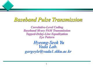
Baseband Signaling and Modulation Part 1: Baseband Signaling Part 1 of a 2-part presentation Eric L. Michelsen
If You Could Tell Your Audience Only One Sentence... Transmitting data requires not only the signaling of bit values, but also bit timing. 1 or 0 time sample here & here & here ... If I could tell them a second sentence, it would be: DC is bad.
Topics: Baseband Signaling (day 1) • On-Off signaling • Antipodal signaling • Timing recovery • NRZI • Multilevel: 2B1Q • DS1 & DS3 • Manchester encoding • 4B/5B encoding • 8B/10B encoding • Multi-Level Transition • A modern line code Topics: Modulation (day 2) • Cosine review • Sums of cosines • Spectra • Fourier transforms • Baseband signaling • Why cosine waves? • Transfer functions • Communication channels as filters • Amplitude modulation • Amplitude demodulation • Quadrature multiplexing • DMT ADSL
DS1 DS3 ADSL IDSL Where in the Stack? • Signaling and modulation are ways of transmitting data • They are the lowest sublayers in Layer 1 (physical layer) • In this context, “signaling” means “transmitting data” (not call setup/teardown) 7. Application OSI stack 6. Presentation 5. Session 4. Transport 3. Network bit serial (payload) V.35, HSSI, SDSL framing framing framing framing framing 2. Link bit serial (line) SONET 1. Physical signaling & modulation electrical optical
A Matter of Values • On-Off binary signaling • simple • indicates 1 (on) or 0 (off) • by itself, does not explicitly convey timing • works for electrical and optical signals • Used by Ethernet 10Base5 and 10Base2 (w/ additional line coding) 1 0 amplitude 1 0 1 1 0 0 time bit period
Time Is of the Essence • With separate clock and data, the transmitter gives the receiver timing on one signal, and data on another • Requires two signals (clock and data): can be expensive • Data values are arbitrary (no restrictions) • Used by local interfaces: V.35, (synchronous) EIA-232, HSSI, etc. • As distance and/or speed increase, clock/data skew destroys timing sample on rising edge of clock clock sample times centered in data bits data time
No Clock: Do You Know Where Your Data Is? • Most long-distance or high speed signaling is self timed: it has no separate clock; the receiver recovers timing from the data itself • Receiver knows the nominal data rate, but requires transitions in the signal to locate the bits, and interpolate the sample points • Receiver tracks the timing continuously, to stay in synch • Tracking requires sufficient transition density throughout the data stream • Used in all DSLs, DS1, DS3, SONET, all Ethernets, etc. transitions locate data data time interpolated sample times (bit centers)
Timing Recovery • All self-timed line codes provide sufficient signal transitions for timing recovery. Some methods used: • Scrambling • Return to zero (RTZ) • Zero substitution • Manchester encoding • 4B/5B • 8B/10B • Multi-level transition
All For One ... or Zero • On-Off binary signaling: simple, but not energy efficient (SNR) • At unit distance (A = 1), average energy = A2/2 = 0.5 • For balanced data, DC (Direct Current) ~= 0.5 (bad) • Also known as Non-Return to Zero (NRZ) • Requires sufficient data transition density, or scrambling • Works for electrical and optical signals 1 0 distance amplitude 1 0 1 1 0 0 time bit period
Pluses and Minuses • Antipodal binary signaling: energy efficient (SNR) • At unit distance (A = 0.5), average energy = A2 = 0.25(3 dB better than on-off signaling) • Requires sufficient data transition density, or scrambling • For balanced (or scrambled) data, DC ~= 0 (good) • For electrical signaling only (negative light?) • Ethernet 10BaseT, EIA-232, V.35, V.36, HSSI +0.5 0 -0.5 1 0 1 1 0 0 amplitude time distance Can you say “tip-ring reversal?”
NRZI (Non-Return to Zero Inverted) • Data value coded as transition = 1, no transition = 0 • Used in combination with antipodal or on/off binary signaling • With scrambling, DC ~= 0 • Why NRZI? Can you say “tip-ring reversal?” • Requires sufficient data 1s (signal transition) density, or scrambling + 0 - ? 1 1 0 1 0 time Equivalent NRZI signals + 0 - ? 1 1 0 1 0 time
Multilevel Signaling: 2B1Q • 4 is better than 2:Encodes 2 Binary bits into 1 Quatenary (4-level) symbol • A pair of bits in a single symbol is a dibit • AKA 4-PAM (4-level Pulse Amplitude Modulation) • Requires data transitions, or scrambling • With scrambling, DC ~= 0 • Used in SDSL, IDSL, ISDN BRI • Other PAMs exist: 16-PAM (G.shdsl), 256-PAM, etc. +3 +1 -1 -3 11 10 01 00 amplitude time Usually described as “distance 2”: -3, -1, +1, +3
AMI: Alternate Mark Inversion • Bipolar, tri-state (+, 0, and -) • 50% duty cycle RTZ (Return To Zero) • Pulses alternate polarity (DC = 0) • Used by DS1 (Digital Service 1, ref. T1.107, T1.403): 2 pair (4 wire) • Line rate = 1.544 Mbps, including 8 kbps framing/OAM • Payload rate = 1.536 Mbps • Generic digital service, can carry T1, PRI, GR-303, Frame Relay, etc. • Timing recovery requires at least 2 pulses (ones) every 16 bits • B8ZS (Binary 8-Zero Substitution) provides transparency mark = 1space = 0 idealized pulse 1 0 1 1 0 0 - amplitude + 25% 50% 25% time alternate polarity UI = Unit Interval (bit period)
AMI: DS3 • Digital Service 3 (ref. T1.107, T1.404): 2 coax, 75 • RTZ (Return To Zero) pulse, very similar to DS1 • AMI (Alternate Mark Inversion), (DC = 0) • Line rate = 44.736 Mbps, including ~530 kbps framing/OAM • Payload rate = 44.736 x (84 / 85) 44.210 Mbps • Generic digital service: can carry T3, Frame Relay, ATM, etc. • Timing recovery requires at least one pulse every 3 bits • B3ZS (Binary 3-Zero Substitution) provides transparency Deliberate bipolar violation, substitutes for 3 zeros 1 0 1 1 0 0 0 0 0 0 - amplitude + X time X bits inserted as needed to make BPVs alternate polarity, to maintain DC = 0 alternate polarity
Double Time: Manchester Encoding • “Coding” in this sense is applicable to any binary (2-state) signal (on-off, antipodal, FSK, etc.) • Provides a transition in the center of every bit • no density requirement • High information content: allows rapid timing recovery • DC = 0, exactly (with antipodal signaling) • Data bit is value in last half of bit (or could be first half) • Used in Ethernet 10Base5, 10Base2, 10BaseT • Equivalent to 1B/2B encoding • Not spectrally efficient: requires transmitting 2 signal events for each bit (100% bandwidth expansion) 1 0 1 1 0 0 signal stateA B time
Enough is Enough: 4B/5B Encoding • Encodes 4 payload bits into 5 line bits • Guarantees transitions; no user data restrictions or scrambling needed • Extra codewords available for control (Idle, SSD, ESD, ...) • More BW efficient than Manchester: 25% expansion • DC >> 0 (bad), but used with NRZI or MLT,DC ~= 0 • Checks line integrity by counting invalid codes • Used in Ethernet 100BaseTX, FDDI Data 0 1 1 1 1 0 1 0 1 0 0 1 2 1 0 1 0 0 3 1 0 1 0 1 4 0 1 0 1 0 5 0 1 0 1 1 6 0 1 1 1 0 7 0 1 1 1 1 8 1 0 0 1 0 9 1 0 0 1 1 A 1 0 1 1 0 B 1 0 1 1 1 C 1 1 0 1 0 D 1 1 0 1 1 E 1 1 1 0 0 F 1 1 1 0 1 Control 1 1 1 1 1 IDLE used as inter-stream fill code 1 1 0 0 0 J Start-of-Stream Delimiter, Part 1 of 2; always used in pairs with K 1 0 0 0 1 K Start-of-Stream Delimiter, Part 2 of 2; always used in pairs with J 0 1 1 0 1 T End-of-Stream Delimiter, Part 1 of 2; always used in pairs with R 0 0 1 1 1 R End-of-Stream Delimiter, Part 2 of 2; always used in pairs with T
Twice as Good: 8B/10B Encoding • Encodes 8 payload bits into 10 line bits • Guarantees 3 to 8 transitions per 10-bit codeword • Maximum run-length of 5 • 25% BW expansion (same as 4B/5B) • 12 control codes (start of packet, end of packet, error, etc.) • Alternately inverts non-zero-DC codewords to achieve zero DC (similar to AMI) • Worst case codeword imbalance is 6/4 • Checks line integrity by counting invalid codes • Used in Gigabit Ethernet, Fiber Channel (FC), some backplanes
Saving Bandwidth:MLT-3 (Multi-Level Transition) • Bipolar, tri-state signal (+, 0, and -) • Like a combination of NRZI and AMI • Transition = data 1, no transition = 0 • Non-zero signals alternate polarity • Cuts bandwidth in half (and SNR as well) • Used by Ethernet 100BaseTX (with 4B/5B and scrambling) 1 0 1 1 0 0 1 1 - amplitude + time distance
A Modern Line Code • Binary signaling (on and off, not dits and dahs) • Pulse Width Modulated (PWM) • Return to zero coded (RTZ, vs. NRZ or NRZI) • Variable rate • Self timed • Asynchronous at word level • Variable length encoding • Data compressed • Forward error corrected (English) A B C D E F G H I J K L M N O P Q R S T U V W X Y Z Interesting history of pen and paper
Just Do It • Receiver recovers unit time interval from dits and inter-symbol spaces; extrapolates other intervals D O I T 7 minimum inter-word space 3 1 1 3 dah size dit size inter-symbol space inter-letter space
Data Compression: English size frequency avg. size frequency avg. A 8 .082 .65 B 12 .014 .17 C 14 .028 .39 D 10 .038 .38 E 4 .131 .52 F 12 .029 .35 G 12 .020 .24 H 10 .053 .53 I 6 .063 .38 J 16 .001 .02 K 12 .004 .05 L 12 .034 .41 M 10 .025 .25 N 8 .071 .57 O 14 .080 1.12 P 14 .020 .28 Q 16 .001 .02 R 10 .068 .68 S 8 .061 .49 T 6 .105 .63 U 10 .025 .25 V 12 .009 .11 W 12 .015 .18 X 14 .002 .02 Y 16 .020 .32 Z 14 .001 .01 Avg letter size: English weighted avg letter size: Opt. Eng. weighted avg letter size: 11.2 units 9.0 (~20% savings) 8.6 (within 5%)
Baseband Summary on-off antipodal multi-level optical
Baseband Signaling and Modulation Part 2: Modulation Eric L. Michelsen
Another Day, Another Sentence Modulation avoids baseband problems of signal overlap and DC error. If I could tell them a second sentence, it would be: Bandwidth is not capacity! If I could tell them a third sentence, it would be: Bandwidth is not capacity! But first, a review of Fourier analysis...
Topics: Modulation • Cosine review • Sums of cosines • Spectra • Fourier transforms • Baseband signaling • Why cosine waves? • Transfer functions • Communication channels as filters • Amplitude modulation • Amplitude demodulation • Quadrature multiplexing • DMT ADSL
Definitions • Baseband signaling • Communicating a signal in its original form for a given medium (e.g., audio) or • Communicating a signal with components down to DC (or almost DC) • Carrier modulation • Communication based on modifying (modulating) a cosine wave signal • Other forms of modulation exist (non-carrier modulation, e.g., PAM, PWM, PCM(?), but that’s another story)
Cosine: A Function of Angle • Basis function for frequency analysis and for modulation 0o 30o 70o 90 180 450 540 angle (degrees) - amplitude + 270 360 630 720 120o one cycle y y y y 30o 120o 70o 0o x x x x 1 unit
Cosine Wave: A Function of Time • Fully characterized by 3 parameters:A Amplitude (e.g., 10 V)f Frequency (e.g., 2 Hz)cosine wave = A cos(f*360t + ) Phase (e.g., 60) = A cos(360ft + ) A = 10 V 10cos(360(2)t + 60o) 60o time (sec) 0.25 0.5 1 f = 2 Hz A 132o 204o 60o 240o t = 0 t = 0.1 t = 0.2 t = 0.25
Sums of Cosines s(t) = A1cos(360f1t) + A2cos(360f2t) + A3cos(360f3t) + ...
Spectrum: A Bar Chart of Cosines • Progressively denser bar charts give way to a simple graph A A f f A A f f
Why Cosine Waves? • Cosines are the onlybasis functions (aka eigenfunctions) of Time Invariant Linear Systems • System: produces output from input • Linear: if Ia Oa, then kIa kOaand if Ib Ob, then (Ia + Ib) Oa + Ob • Time invariant: it does the same thing all the time • If input is a cosine, then output is a cosine of same frequency, but different amplitude and phase • Linear Cosine components of input don’t interact output is cosine of exactly the same frequency... input is any cosine TILS ...but different amplitude and phase time time
Triangles Are Not Cosines • If input is not a cosine, output is not a multiple of the input • Single triangle wave input produces complex output • What a mess! input is a triangle wave output is NOT a triangle wave TILS time time
time Transfer Functions • A TILS multiplies each input frequency amplitude (& shifts its phase) • The multiplier (and phase-shift) are functions of frequency TILS H(f ) = Aout / Ain or Aout = H(f )Ain Ain Aout time at same frequency, f at frequency, f • We can graph the amplitude multiplier as a function of frequency, the amplitude transfer function, H(f ): We can graph the phase-shift as a function of frequency: the phase transfer function, (f )(but we won’t) H(f ) f
Transfer Functions at Work • Since cosine components of the input signal do not interact, each cosine is multiplied by the transfer function at its frequency • Thus, the output spectrum is the input spectrum multiplied by the transfer function, at each frequency • Every TILS has a transfer function, and a transfer function defines a TILS. TILS Input signal spectrum Transfer function of linear system Output signal spectrum
The Communication Channel as Filter • Any communication channel is imperfect • A time invariant linear channel is described by its transfer function • A filter is a TILS that passes some frequencies, and blocks others Transfer function for a copper loop H(f ) f Transfer function for a copper loop with a splitter H(f ) f Transfer function for a transistor amplifier H(f ) This is why DC is bad. f
The Spectrum of Square Wave Antipodal Signaling • 90+% of energy is in the first lobe • Part of the first, and all of the other lobes can be discarded without much degradation • This is also the spectrum of 2B1Q, and all PAMs A time fsym 2fsym 3fsym square wave A time fsym 2fsym 3fsym filtered square wave
Amplitude Modulation • Given a signal, i(t) • And a carrier, cos(360ct) • We modulate the signal onto the carrier by multiplying the two at each instant in time: i(t)cos(360ct) cos(360ct) x i(t) modulator i(t) = cos(360ct) i(t)cos(360ct)
1. cos(-a) = cos(a) 2. cos(90-a) = -cos(90+a) 3. cos(a+b) = cos(a)cos(b) - cos(90-a)cos(90-b) cos(a - b) + cos(a + b) 2 4. cos(a)cos(b) = Know Your Identity cos(90-a)cos(90-b) 90-b Demonstration of identity #3 cos(90-a) 90-a b Recall that for any right triangle: 1 unit cos(a) H a a b H•cos(a) cos(90-a)cos(90-b) cos(a+b) cos(a)cos(b)
Spectral View of Amplitude Modulation • Modulating a baseband cosine onto a carrier i(t) = cos(360wt) (simple) baseband spectrum: a cosine of frequency ‘w’ A f w cos(360ct) carrier spectrum:a cosine of frequency ‘c’ A f c Modulated signal spectrum:Using identity #4: cos(360wt)cos(360ct) = cos[360(c-w)t] + cos[360(c+w)t] A f Pop Quiz: Is a modulator a TILS? c-w c c+w
Deja View of Amplitude Modulation • Modulating a complicated baseband signal onto a carrier i(t) complicatedbaseband spectrum (AM radio BW = 5 kHz) A f bandwidth cos(360ct) A carrier spectrum (AM radio carrier = 540 - 1600 kHz) f c Modulated signal spectrum;using identity #4 for each frequency component A Notice that the modulated bandwidth is twice the baseband signal bandwidth (AM radio BW = 10 kHz) f c bandwidth
Demodulation: Getting It Back • Given a modulated signal: i(t)cos(360ct) • Multiply by the carrier again: i(t)cos(360ct)cos(360ct)= i(t)[cos(0) + cos(360(2ct))] = i(t)+ i(t)cos[360(2ct)] modulated spectrum A f c i(t)cos[360(2ct)] almost demodulated spectrum i(t) A f c 2c filtered and fully demodulated spectrum filter transfer function A f c 2c
All Together Now A time fsym 2fsym 3fsym Energy Efficient Signaling A time fsym 2fsym 3fsym Filtered Baseband Signal A c Modulated Carrier
Comparison of Modulated and Unmodulated Carrier - + unmodulated carrier modulated carrier
Quadrature Multiplexing: Two for the Bandwidth of One • Consider a signal modulated with the wrong carrier phase, off by 90. We attempt to demodulate (recall identity #4): i(t)cos(360ct + 90)cos(360ct)= i(t)[cos(90) + cos(360(2ct) + 90)] = i(t)cos[360(2ct) + 90] modulated spectrum A f c attempted demodulated spectrum i(t)cos[360(2ct) + 90] A f c 2c filtered signal spectrum filter transfer function A f
Quadrature Multiplexing: Part Deux • Consider two signals, i(t) and q(t), modulated with two carriers of the same frequency, but different by 90: i(t)cos(360ct) + q(t)cos(360ct + 90) i(t) q(t) baseband spectra A A f f modulated signal spectrum: generally not symmetric A f c
Quadrature Demodulation • Given a quadrature multiplexed modulated signal: i(t)cos(360ct) + q(t)cos(360ct + 90) • Demodulate each channel separately, each with its own carrier: carrier for i(t) [ i(t)cos(360ct) + q(t)cos(360ct + 90) ]cos(360ct) = i(t)cos(360ct)cos(360ct) + q(t)cos(360ct+90)cos(360ct) i(t) demodulated spectrum A f c 2c carrier for q(t) [ i(t)cos(360ct) + q(t)cos(360ct + 90) ]cos(360ct + 90) = i(t)cos(360ct)cos(360ct+90) + q(t)cos(360ct+90)cos(360ct+90) q(t) demodulated spectrum A c 2c f
DMT ADSL • Discrete Multi-Tone • Up to 255 “separate” carriers, • Each carrier is quadrature multiplexed multi-level PAM • Two to 15 bits per symbol per carrier (2 - 256 PAM per I/Q axis) • Optimum filling of data into the carriers for maximum total SNR • All share the same time, frequency, and phase references • Lower carriers omitted for baseband voice • Carrier spacing is 4312.5 Hz upstream downstream A baseband voice f N x 4312.5 Hz 300 Hz 3600 Hz
DMT ADSL • Two kinds of FEC: • “Fast” path (low latency): Trellis Coded Modulation (TCM) • “Interleaved” path (higher latency): Reed-Solomon block interleaved • Framing structure built into the modulation • Integral number of bytes per frame, 4000 user data frames per second = N x 32 kbps data rates • G992.1 defines two services: STM and ATM • The industry standard is ATM over STM (HEC delineation) • No one uses G992.1’s ATM mode Superframe: 17 ms frame 0 frame 0 frame 1 frame 2 frame 3 ... frame 66 frame 67 synch symbol over head Fast bytes over head FEC over head Interleaved bytes over head