Download
1 / 13
130 likes | 138 Views
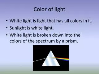
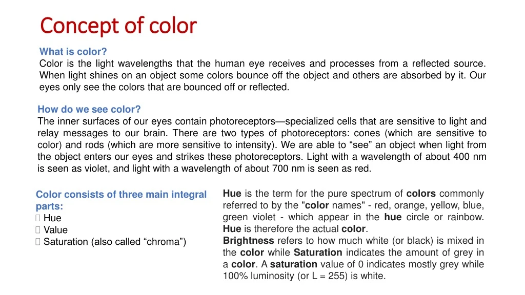
Concept of color. What is color? Color is the light wavelengths that the human eye receives and processes from a reflected source. When light shines on an object some colors bounce off the object and others are absorbed by it. Our eyes only see the colors that are bounced off or reflected.

E N D
Concept of color What is color? Color is the light wavelengths that the human eye receives and processes from a reflected source.When light shines on an object some colors bounce off the object and others are absorbed by it. Our eyes only see the colors that are bounced off or reflected. How do we see color? The inner surfaces of our eyes contain photoreceptors—specialized cells that are sensitive to light and relay messages to our brain. There are two types of photoreceptors: cones (which are sensitive to color) and rods (which are more sensitive to intensity). We are able to “see” an object when light from the object enters our eyes and strikes these photoreceptors. Light with a wavelength of about 400 nm is seen as violet, and light with a wavelength of about 700 nm is seen as red. • Color consists of three main integral parts: • Hue • Value • Saturation (also called “chroma”) Hue is the term for the pure spectrum of colors commonly referred to by the "color names" - red, orange, yellow, blue, green violet - which appear in the hue circle or rainbow. Hue is therefore the actual color. Brightness refers to how much white (or black) is mixed in the color while Saturation indicates the amount of grey in a color. A saturation value of 0 indicates mostly grey while 100% luminosity (or L = 255) is white.
Primary, secondary, and tertiary hues Hues The three primary hues in light are red, green, and blue. Thus, that is why televisions, computer monitors, and other full-range, electronic color visual displays use a triad of red, green, and blue phosphors to produce all electronically communicated color. Mixing Adjacent Primaries = Secondary Hues Mixing Primary and Secondary =Tertiary Hues The colors on the outermost perimeter of the color circle are the”hues,” which are colors in their purest form. The next level colors, the tertiary colors, are those colors between the secondary and primary colors. The secondary colors are produced when RGB light hues are mixed, as follows: Blue + Red light –> Magenta Red + Green light –> Yellow Green + Blue light –> Cyan
Saturation Saturation is also referred to as “intensity” and “chroma.” It refers to the dominance of hue in the color. On the outer edge of the hue wheel are the ‘pure’ hues. As you move into the center of the wheel, the hue we are using to describe the color dominates less and less. When you reach the center of the wheel, no hue dominates. These colors directly on the central axis are considered desaturated. Naturally, the opposite of the image above is to saturate color.
Value Value is the dimension of lightness/darkness. In terms of a spectral definition of color, value describes the overall intensity or strength of the light. If hue can be thought of as a dimension going around a wheel, then value is a linear axis running through the middle of the wheel, as seen below: Pigment Scale Light Scale
Principles of colour transmission To meet the requirements of compatibility, the luminance signal Y is transmitted in the same way as in a monochrome system within which the chrominance is be contained. The next step is to produce the pure chrominance component from the RGB signal. To do this, the luminance had to be removed from the three primary colours, resulting in what is known as colour difference signals: R – Y, G – Y and B – Y. Since the luminance signal Y = R + G + B, and luminance Y is to be transmitted in full, only two colour difference signals need to be transmitted. Of the three colour difference signals, Y – G normally has the smallest value. For this reason, difference signals (R – Y) and (B – Y) are selected. The missing (G – Y) is recovered at the receiving end from the three transmitted components as follows: The remaining issue that has to be resolved is the manner in which this additional information, R – Y and B – Y, is added to the monochrome signal without causing it any interference. To do this, a separate colour subcarrier [4.43 MHz for Phase Alternate Line (PAL) and 3.58 MHz for National Television System Committee (NTSC)] is introduced which is then modulated by the two-chrominance components using quadrature amplitude modulation (QAM).
Frequency interleaving • Since the modulated colour subcarrier falls within the monochrome frequency spectrum, its sidebands naturally overlap with those produced by the original vision carrier. This overlap will result in pronounced patterning on a monochrome set receiving colour transmission. This is avoided by the choice of the subcarrier frequency resulting in what is known as frequency interleaving. When the frequency spectrum of a TV signal is examined in detail, it is found that the distribution of frequencies is not uniform. Energy tends to gather in bunches centred on the harmonics, i.e. multiples of line frequency, known as monochrome clusters as shown in Fig. Furthermore, the amplitude of these side frequencies gets progressively smaller as we move away from the vision carrier. Similarly, colour information would also bunch into chrominance clusters. By choosing the subcarrier to fall between two monochrome clusters, the chrominance clusters may be arranged to fall in the spectrum.
Composite video signal • Composite means that the video signal includes several parts. • These parts are: • Camera signal corresponding to the desired picture information • Synchronizing pulses to synchronize the transmitter and receiver scanning • Blanking pulses to make the retrace invisible • These three components are added to produce the composite video signal.
Composite video signal The technique of compatible colour television utilizes two transmissions. One of these carries information about the brightness, or luminance, of the televised scene, and the other carries the colour, or chrominance, information.
Block diagram of color TV receiver Super-heterodyne section: • It is similar to the super-heterodyne section in a monochrome receiver except that the inter-carrier frequency signal is taken out (for sound section) from the last IF stage instead of from the output of the detector or video pre-amplifier. • The reason for this is to save the picture from the beat signal produced by mixing chroma signal (3.58MHz) with inter-carrier frequency (4.5MHz). • Beat of the two signals would be 920 kHz in NTSC system which falls within the video bandwidth and would cause interference known as sound in picture. Tuner Sound section. IF stages Inter-carrier freq. det. IC amp. FM det. Audio amp. Superhetorodyne section Video section. Video det. Video pre-amp. Video power amp. Delay line Y, Luminescence signal R-Y Matrix circuits Adder Display device Color driver U PAL color decoder B-Y C, Chrominance signal Color driver V G-Y AGC Color driver Color decoding section. V-deflection current Deflection circuits H-deflection current Deflection section.
Block diagram of color TV receiver Video section: • Video detector recovers composite color video signal (CCVS) signal. Luminance signal (Y) is amplified and is delayed by a delay line so that it reaches the adder simultaneously with the chroma signal. • Chroma signal propagated slowly in the colour decoder circuit due to lower bandwidth and hence Y signal has to be delayed. Colour decoder: • CCVS signal is available at the video detector’s output. It goes to the video pre-amplifier which amplifies the CCVS signal. • The effective bandwidth of Y signal for colour receiver is about 3.13MHz (1.3MHz lower than 4.43MHz). • Y signal is separated from C signal either by using a comb filter or preferably by a simple bandpass filter to pass a bandwidth of 3.13MHz. • Y signal goes to the video power amplifier and C goes to the colour decoder. There are two types of colour decoders: Simple PAL and Delay line PAL.
• Chroma signal is duly amplified by bandpassamplifier BPA-I and BPA-ii and is fed to two detectors (BM-I and BM-II) of the balanced modulator type. • The subcarrier generator generates 4.43MHz signal which is correctly synchronized to the one used in the transmitter with the help of colour burst (CB) signal and automatic frequency and phase control circuit (AFPC). • The CB signal is separated out from the CCVS signal by a CB separator stage which uses a class C amplifier. • The subcarrier signal also is fed to two balanced demodulators (BM-I and BM-II). To BM-I, it goes with zero phase but to BM-II its phase changes by 90 degree for out line and -90 degree for the next line with the help of an automatic electronic switch controlled by pulses produced by a bi-stable multi-vibrator. • The detection is synchronous or coherent. Hence BM-I detector detects U signal as phase of U as well of the subcarrier is zero. It does not detect V signal because V signal’s phase is 90 degree. • V signal is detected by BM-II detector because the phase of V as well as of the subcarrier is 90 degree. Thus BM-I detector gives U and BM-II detector gives V at their respective outputs. Simple PAL color decoder • These signals are de-weighted to the original colour difference signals (B-Y) and (R-Y) by using amplifiers. The third colour difference signal G-Y is obtained by the respective matrix using the following relation: 0.59 (G-Y) + 0.3 (R-Y) + 0.11 (B-Y) = 0 • The three colour difference signals are fed to the adders along with Y signal from the delay line of video section. Addition of Y to colour difference signals gives R, G and B signals.
Deflection circuit Deflection circuits: • Deflection circuits for colour receiver are similar to that in a monochrome system except that additional currents for removing pincushion effect are made available for the deflection yoke. • Colour picture tube required for this section is totally different from the monochrome picture tube. • The three signals duly amplified are fed to the input of the three electron guns of the colour picture tube. • The three beams coming out of the electron guns get intensity modulated by the three colour signals and glow the three phosphor dots (in delta picture tube) or three stripes (in PIL picture tube). • The eye preforms additive mixing of the three colours and therefore sees the original colour of the picture which has been transmitted.