Download
1 / 101
1.01k likes | 1.03k Views
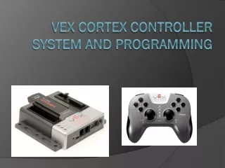
Vex Cortex Controller System and Programming. Who are we? . Naomi Fitzsimmons naomi.fitzsimmons@student.oc.edu Parts replacement Matt Lapolla okbest@mattandsuz.com Programming, Technical issues, Rules, etc. John Robertson johndrobertson@gmail.com Policies, Technical Issues, Scoring

E N D
Who are we? • Naomi Fitzsimmons • naomi.fitzsimmons@student.oc.edu • Parts replacement • Matt Lapolla • okbest@mattandsuz.com • Programming, Technical issues, Rules, etc. • John Robertson • johndrobertson@gmail.com • Policies, Technical Issues, Scoring • Bill Ryan • Bill.Ryan@oc.edu • Everything else
Overview • Terminology • Hardware Overview • Programming Languages • Programming example • Defining Inputs • Defining Outputs • Input - Output Relationship • Write Program • Test Program • Other Useful Functions • Appendix
Terminology: Proportional or Non-Proportional Dimmer Light Switch Regular Light Switch Non-Proportional (Digital) Proportional (Analog)
Terminology: Motor with Limit Transmitter Cortex
Servo vs Motor Robot Transmitter 0 32 64 127 -32 -64 -127 QUESTIONS? Cortex Controller Motor Servo
Terminology: Programming software • Compile – changes your C program into object code that the linker understands. • Link – combines your program’s object code with the Intelitek library and other libraries to create code that is executable on the Cortex processor. • Download / Bootload – transfers the machine code version of your program from the PC to the Cortex where it will execute (the IFI/Intelitek Loader will perform the transfer via the PC USB cable)
Servos Return Kit Joystick USB/Tether WiFi key Serial AAA Battery Charger Analog Picture Not Available Digital i/o Servo Extensions motors/ servos (2) Servo Power Adaptor Controller battery (2) Servo Horns (4) USB A-A cable (2) Servo Mount H/W (16) (2)
Drive components Return Kit (2) Motors 7.2V Battery charger Picture Not Available (2) Motor controller (4) Battery adapter Screw terminal sensor i/f cable (8) (2) 7.2V Battery (2) Screw terminal motor i/f cable (4)
Hardware Overview: Joystick 8 buttons on top 2 XY analog joysticks 6 AAA rechargeable batteries Power switch Plug-in USB/ WiFi Key 4 Button on front-side Partner/ Buddy Control Support 3 Axis Accelerometer (XY Tilt, XYZ Accel, Shake)
Hardware Overview: Joystick – What you will use 8 buttons on top 2 XY analog joysticks 6 AAA rechargeable batteries Power switch Plug-in USB/ WiFi Key 4 Button on front-side Partner/ Buddy Control Support 3 Axis Accelerometer (XY Tilt, XYZ Accel, Shake) 3 Axis Accelerometer (XY Tilt)
Hardware Overview: Cortex Controller USB Standard Serial Interfaces (UART, I2C) 1 Analog in 8 2-wire motor 1 1 2 Digital in/out 3-wire PWM servo/motor ctrl 12 9 Speaker Out SP 10 2-wire motor
Hardware Overview: Cortex Controller – What you will use USB Standard Serial Interfaces (UART, I2C) 1 Analog in 8 2-wire motor 1 1 2 Digital in/out Digital in 3-wire PWM servo/motor ctrl 12 9 Speaker Out SP 10 2-wire motor
Hardware Overview: Cortex Controller This will only be important on Game Day. Install before each match. Remove after each match. configuration switch (used for special procedures) 75MHz crystal interface ports On/Off switch backup battery port for WiFi communications (9V) main battery port (7.2V)
Hardware Overview: Cortex Controller – What you will use configuration switch (used for special procedures) 75MHz crystal interface ports On/Off switch backup battery port for WiFi communications (9V) main battery port (7.2V)
Ground + 5V Signal/Control + Battery Power + Motor Power (for + control input) - Motor Power (for – control input) Hardware Overview: Cortex Controller
Hardware Overview:DC Motors Do not solder to motors. Use spade connectors instead. Polarity is NOT marked on motors: positive(+), negative(-) Wiring and programming will determine clockwise or counter clockwise rotation for positive stick movement Mount motors with VEX Motor Mounting Kit
Hardware Overview:DC Motors • For power reasons, spread your motors so that you have • no more than 2 motors plugged into ports 2-5 and • no more than 2 motors plugged into ports 6-9. • You risk overcurrent and shutdown of the processor. • Servo/motor ports are divided into 2 banks • Bank1 = Ports 1-5 • Bank2 = Ports 6-10 • Each bank can support a maximum of 4 Amps of current • BEST large motor stall current can reach 3.5 Amps. • Sheet metal shield around the large motors IS needed and should not be removed.
Hardware Overview:DC Motors • If using built-in motor controller(s) • connect via 2-wire screw terminal cables (red/black) • use motor ports 1 & 10 only • If using external motor controller(s) • connect via 3-wire external motor controller + 2-wire screw terminal cable • use motor ports 2 thru 9 only
Hardware Overview: 2 wire Motor connection Ports 1, 10 Screw terminals for attaching motor wires Connector is not keyed. Allows swapping polarity. Port 1 and Port 10 Built-In Motor Controllers
Hardware Overview: 3 wire Motor connection Ports 2 - 9 Suggest using a 4” wire tie or heat shrink tubing here External Motor Controller Standard 2-wire motor cable Standard 3-wire PWM connector Plug in to Motor Ports 2 thru 9 Screw terminals for attaching motor leads
Hardware Overview: Servo – Electrical Connection White to White Black to Black • Futaba S3003 or S3004 series • Maximum 120 degree rotation (+60, -60) • Connection to Cortex controller • use motor ports 2 thru 9 only • Servo horns may be modified 2x3 pin header Servo Power Adapter Cable via 3-wire PWM + 2x3 pin header servo horns (2) (2) (1)
Hardware Overview: Servo – Electrical Connection Insert a 2x3 pin header Occupies 2 ports Converts VEX female port to male port Because Futaba servos have female connectors
Hardware Overview:Servo – Electrical Connection • Insert a Servo Power Adaptor • Converts VEX female port to male port and provides protection • Because Futaba servos have female connectors
Hardware Overview: Servo – Electrical Connection Servo connectors are keyed for proper insertion. (small tab shown) Servo Cables White= Data Red = +Batt Voltage Black = Gnd Second half of 2x3 pin header.
Hardware Overview: Servo – Mounting Hardware • Futaba 3003/3004 Servos • 4 per Kit • Mounting Hardware for each • To eliminate damage to mounting holes • Servo Mounting Hardware • Rubber grommet (2) • Brass spacer (4) • Mounting screw (4) Note: There are 16 of each screw, spacer, grommet in the Return Kit.
Hardware Overview: Servo – Mounting Hardware 1. No h/w attached 2. Attach rubber grommets 3. Insert brass spacers 4. Secure servo with screws
Hardware Overview: Digital Input/Output Use for switches Connect to Cortex digital inputs using 2-wire sensor screw terminal cables (white/black wires) sensor screw terminal cable Connect to switch Connect to Cortex digital input port
Hardware Overview: Digital Input / Output must program digital port for proper direction (input) Open: Program reads as ‘1’ ; Closed: Program Reads as ‘0’ sensor cable connector is keyed use digital ports 1 thru 12
Programming Languages • Three different programming environments available • MathWorks Simulink http://www.mathworks.com/academia/best-robotics/ • easyCv4 http://www.intelitekdownloads.com/easyCV4 • RobotC http://www.robotc.net/download/cortex
Programming Languages: Simulink • Simulink is graphical programming/modeling environment • Simulation capability (see what your program will do before you download it to the Cortex)
Programming Languages: Robot C • RobotC programs in C with a text editor, but it has runtime debugging (can step through program line by line and see what the results are)
Programming Languages: Easy C • easyC is a block programming environment (similar to software for Lego Mindstorms)
Programming Example:Steps to creating a program • Open new Easy C workspace • Define Inputs • Define Outputs • Define Input to Output relationship • Write a program • Compile Program • Download • Test Program
Programming Example Defining Inputs
Defining Inputs: Joystick, Switches and Digital Signals • What are the Inputs? Joystick Input Options Proportional Channel 1 Channel 2 Channel 3 Channel 4 Tilt X Tilt Y Digital Inputs Channel 5 Up, Down Channel 6 Up, Down Channel 7 U, D, R, L Channel 8 U, D, R, L Controller Input Options Digital 1 Digital 2 Digital 3 Digital 4 Digital 5 Digital 6 Digital 7 Digital 8 Digital 9 Digital 10 Digital 11 Digital 12
Defining Inputs: Joystick, Switches and Digital Signals • Channel 1 • Drive: Turn Right Left • Channel 2 • Drive: Forward/Reverse Joystick Input Options Proportional Channel 1 Channel 2 Channel 3 Channel 4 Tilt X Tilt Y Digital Inputs Channel 5 Up, Down Channel 6 Up, Down Channel 7 U, D, R, L Channel 8 U, D, R, L Controller Input Options Digital 1 Digital 2 Digital 3 Digital 4 Digital 5 Digital 6 Digital 7 Digital 8 Digital 9 Digital 10 Digital 11 Digital 12
Defining Inputs: Joystick, Switches and Digital Signals • Channel 1 • Drive: Turn Right Left • Channel 2 • Drive: Forward/Reverse • Channel 3 • Arm: Raise and Lower Joystick Input Options Proportional Channel 1 Channel 2 Channel 3 Channel 4 Tilt X Tilt Y Digital Inputs Channel 5 Up, Down Channel 6 Up, Down Channel 7 U, D, R, L Channel 8 U, D, R, L Controller Input Options Digital 1 Digital 2 Digital 3 Digital 4 Digital 5 Digital 6 Digital 7 Digital 8 Digital 9 Digital 10 Digital 11 Digital 12
Defining Inputs: Joystick, Switches and Digital Signals • Channel 1 • Drive: Turn Right Left • Channel 2 • Drive: Forward/Reverse • Channel 3 • Arm: Raise and Lower • Digital 1 • Arm: Upper Limit • Digital 2 • Arm: Lower Limit Joystick Input Options Proportional Channel 1 Channel 2 Channel 3 Channel 4 Tilt X Tilt Y Digital Inputs Channel 5 Up, Down Channel 6 Up, Down Channel 7 U, D, R, L Channel 8 U, D, R, L Controller Input Options Digital 1 Digital 2 Digital 3 Digital 4 Digital 5 Digital 6 Digital 7 Digital 8 Digital 9 Digital 10 Digital 11 Digital 12
Defining Inputs: Joystick, Switches and Digital Signals • Channel 1 • Drive: Turn Right Left • Channel 2 • Drive: Forward/Reverse • Channel 3 • Arm: Raise and Lower • Digital 1 • Arm: Upper Limit • Digital 2 • Arm: Lower Limit • Channel 5 Up • Wrist: Rotate Up • Channel 5 Down • Wrist: Rotate Down Joystick Input Options Proportional Channel 1 Channel 2 Channel 3 Channel 4 Tilt X Tilt Y Digital Inputs Channel 5 Up, Down Channel 6 Up, Down Channel 7 U, D, R, L Channel 8 U, D, R, L Controller Input Options Digital 1 Digital 2 Digital 3 Digital 4 Digital 5 Digital 6 Digital 7 Digital 8 Digital 9 Digital 10 Digital 11 Digital 12
Programming Example Defining Outputs