Download
1 / 29
300 likes | 421 Views
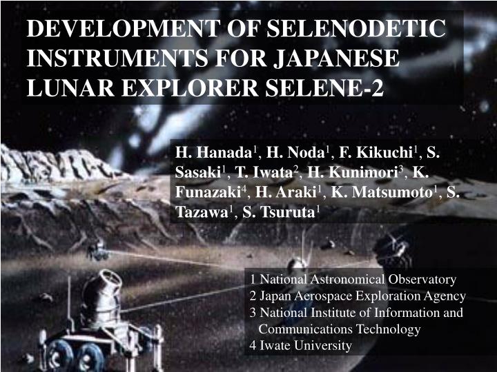
DEVELOPMENT OF SELENODETIC INSTRUMENTS FOR JAPANESE LUNAR EXPLORER SELENE-2. H. Hanada 1 , H. Noda 1 , F. Kikuchi 1 , S. Sasaki 1 , T. Iwata 2 , H. Kunimori 3 , K. Funazaki 4 , H. Araki 1 , K. Matsumoto 1 , S. Tazawa 1 , S. Tsuruta 1. 1 National Astronomical Observatory

E N D
DEVELOPMENT OF SELENODETIC INSTRUMENTS FOR JAPANESE LUNAR EXPLORER SELENE-2 H. Hanada1, H. Noda1, F. Kikuchi1, S. Sasaki1, T. Iwata2, H. Kunimori3, K. Funazaki4, H. Araki1, K. Matsumoto1, S. Tazawa1, S. Tsuruta1 1 National Astronomical Observatory 2 Japan Aerospace Exploration Agency 3 National Institute of Information and Communications Technology 4 Iwate University
KAGUYA (SELENE) → SELENE-2 • Successful KAGUYA • Study of lunar landing mission(s) in JAPAN. • SELENE-2 lunar lander • SELENE Series 2, 3, …X • Launch by H-IIA in 2016 ? • Lander of 1000kgincluding scientific instruments of 300kg
Mission instruments for SELENE-2 • Scientific instruments • Science of the moon • Geophysical/geodetic instruments • Geological instruments • Science from the moon • Astronomical instruments • Engineering instruments • Environmental instruments
Proposal for SELENE-2 SELENE-2 instruments for Lunar intererior study ◆Gravity observations by VLBI (Same-beam and Inverse VLBI) ◆Rotation observations by Lunar Laser Ranging (new reflectors and a new ground network) They are under review for onboard instruments Another rotation observations by ILOM (In-situ Lunar Orientation Measurement) is proposed for SELENE-3
Selenodetic Candidate instruments • Questions to be addressed: • Is there a core in the Moon ? • Is the core metallic ? • Is the metallic core liquid ? • Is there an inner core center of the liquid core ?
Lunar Laser Ranging Laser Ranging from the Earth to the Moon started by Apollo in 1969 and continue to the present 4 reflectors are ranged: Apollo 11, 14 & 15 sites Lunakhod 2 Rover LLR attained the accuracy of less than 3cm with observations for longer than 25 years.
Objectivesof future LLR • Ephemerides and/or Reference systems • Gravitational physics (General Relativity) • Geodynamics • Lunar science and Selenophysics
Issues on LLR Deployment:Where on the Moon ? Type: “Array” or “Single”, “Prism or Hollow” Size:Reflection Efficiency more than A11 or A15 Structure: Hard to be affected by gravitational and thermal effects Optical Performance:Ray tracing simulation Dihedral Angle Offset:What is the optimal value ? Adaptive Optics:Option
Deployment :Where on the Moon ? ●Area: Data Contribution (~77%) 新規? 2,000km For Physical Librations: Southern Hemispherefar from A15 site about 2000km or more Schickard (44.3S, 55.3W) Tycho(43.4S,11.1W)
Type : Array or Single, Prism or Hollow ? • Prism array of small aperture (Apollo, Luna) • Large range error due to optical libration • Single prism with large aperture • High accuracy of ranging • Extremely high quality prism is necessary : ⇒less than 10cm size CCP • Single hollow with large aperture • Lighter weight • High accuracy • Change of dihedral angle due to thermal distortion will be a problem
Structure : Deformation by Earth’s Gravity L D D=20 cm (L = 14.14 cm), t = 1cm, “Cu” Deformation:less than 1 μm by Earth’s Gravity Field Taniguchi, 2010
Structure : Thermal Deformation of CCR (mm) (mm) L D L= 7.07 cm (D=10cm), < 3 nm L=14.14 cm (D=20cm), < 60 nm NEC, 2010
Optical Performance (Ray Tracing Analysis) Efficiency (Streal Ratio) : 95.8 % L=14.14 cm (D=20cm), < 60nm Kashima, 2010
VLBI (Very Long Baseline Interferometer)? Quasar Noise Noise
VLBI : Improvement of Lunar Gravity field Orbiter Same-beam (Differential) VLBI Method ◇Doubly Differenced One-way Range Sensitivity : <20 cm Survival module Inverse VLBI Method ◇Differenced One-way Range ◇2-way range between orbiter and S-module Sensitivity : <10-20 cm These new observations are expected to improve the lunar gravity field.
Inverse VLBI • Radio signals transmitted from orbiter and lander are received at a ground antenna. These signals are synchronized via a reference signal from orbiter. • Received signals are cross correlated and a difference of the propagation time is measured. • Expected accuracy is several tens to several ps. These time difference corresponds to the distance of a few cm to a few mm.
Same-beam VLBI method : Improvement of lunar gravity model Simulation result 2nd degree coefficients are improved by factor 3 or more. Moment of inertia Topography, Moho, GRAIL/LRO/Kaguya data Constrain core density and radius
Conditions of the Simulations Orbit parameters : Perilune height = 100km, Apolune height = 800km, Orbit inclination = 70° Landing position : (0°、0°) Tracking station : Usuda(64m) and VERA(20m) Data weight: 2-way Doppler = 1 mm/s, VLBI= 1 mm Arc length of orbiter : 14 days. Observation Period : 3 months
In-situ Lunar Orientation Measurement (ILOM)
Principle of ILOM Observations Telescope Motion of a star in the view Other objectives than lunar rotation Pilot of lunar telescope (Engineering) Establishment of a lunar coordinate system
Star trajectory and Effects of Librations After Heki Trajectory of a star observed at the Lunar pole (June 2006– Sep.2007) Decomposition of the trajectory Polar motion and Librations extracted from the trajectory
0.1m Development of BBM (Cooperation with Iwate univ.) Objective Motor 0.5m Frame Tube Mercury Pool Tiltmeter Tripod After Iwate Univ.
Issues on ILOM: Technical issues Improvement of the accuracy of centroid experiments Correction of effects of temperature change upon star position Keeping power during the night Keeping warm during the night Keeping inside thermally stable Important condition of the lunar surface ? How is the lunar dust ? How dark is the lunar surface at night ? How stable is the lunar surface ? How quiet is the lunar surface ?
Summary • Technical developments and scientific evaluations for LLR, VLBI and ILOM are going on. • LLR and VLBI instruments are under review for SELENE-2 onboard instruments. • ILOM is prepared for SELENE-3. • We will investigate the lunar deep interior by further improving accuracy of observations of the lunar rotation and the gravity fields with new technologies.
Fabrication of CCR http://www.jst.go.jp/pr/info/info96/zu1.html • ELID and Electroforming : with Omori Lab., RIKEN Inst. ELID (Electrolytic Inprocess Dressing) For making the “Master” of CCR Surface Roughness: ±10 nm Electroforming [Electrolysis] Fabrication of One-unit CCR from “Cu” • Now trying to make a surface with Cu