Download
1 / 38
380 likes | 700 Views
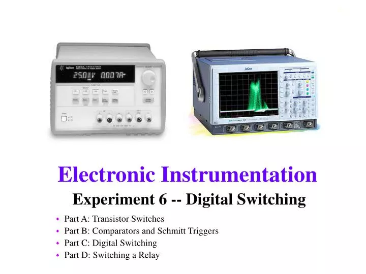
Experiment 6 -- Digital Switching. Part A: Transistor Switches Part B: Comparators and Schmitt Triggers Part C: Digital Switching Part D: Switching a Relay. Part A: Transistors. Analog Circuits vs. Digital Circuits Bipolar Junction Transistors Transistor Characteristics

E N D
Experiment 6 -- Digital Switching Part A: Transistor Switches Part B: Comparators and Schmitt Triggers Part C: Digital Switching Part D: Switching a Relay
Part A: Transistors • Analog Circuits vs. Digital Circuits • Bipolar Junction Transistors • Transistor Characteristics • Using Transistors as Switches
Analog Circuits vs. Digital Circuits • Ananalog signal is an electric signal whose value varies continuously over time. • A digital signal can take on only finite values as the input varies over time.
A binary signal, the most common digital signal, is a signal that can take only one of two discrete values and is therefore characterized by transitions between two states. • In binary arithmetic, the two discrete values f1 and f0 are represented by the numbers 1 and 0, respectively.
In binary voltage waveforms, these values are represented by two voltage levels. • In TTL convention, these values are nominally 5V and 0V, respectively. • Note that in a binary waveform, knowledge of the transition between one state and another is equivalent to knowledge of the state. Thus, digital logic circuits can operate by detecting transitions between voltage levels. The transitions are called edges and can be positive (f0 to f1) or negative (f1 to f0).
Bipolar Junction Transistors • The bipolar junction transistor (BJT) is the salient invention that led to the electronic age, integrated circuits, and ultimately the entire digital world. The transistor is the principal active device in electrical circuits. • When inputs are kept relatively small, the transistor serves as an amplifier. When the transistor is overdriven, it acts as a switch, a mode most useful in digital electronics.
B • There are two types of BJTs, npn and pnp, and the three layers are called collector (C), base (B), and emitter (E). npn transistor E C • All current directions are reversed from the npn-type to the pnp-type. • A BJT consists of three adjacent regions of doped silicon, each of which is connected to an external lead. The base, a very thin slice of one type, is sandwiched by the complementary pair of the other type, hence the name bipolar.
FET, Field Effect Transistors, are another type of transistor. They are the basis of most logic, memory and microprocessor chips. • Applying a gate voltage that exceeds the threshold voltage opens up the channel between the source and the drain • This is from an excellent collection of java applets at SUNY Buffalo http://jas.eng.buffalo.edu/
pnp and npn transistors Note: The npn-type is the more popular; it is faster and costs less. VCE > 0 VBE > 0 VCE < 0 VBE < 0 pnp BJT npn BJT Apply voltage LOW to base to turn ON Apply voltage HIGH to base to turn ON
Characteristics of Transistors • Cutoff Region • Not enough voltage at B for the diode to turn on. • No current flows from C to E and the voltage at C is Vcc. • Saturation Region • The voltage at B exceeds 0.7 volts, the diode turns on and the maximum amount of current flows from C to E. • The voltage drop from C to E in this region is about 0.2V but we often assume it is zero in this class. • Active Region • As voltage at B increases, the diode begins to turn on and small amounts of current start to flow through into the doped region. A larger current proportional to IB, flows from C to E. • As the diode goes from the cutoff region to the saturation region, the voltage from C to E gradually decreases from Vcc to 0.2V.
The diode is controlled by the voltage at B. • When the diode is completely on, the switch is closed. This is the saturation region. • When the diode is completely off, the switch is open. This is the cutoff region. • When the diode is in between we are in the active region. Diode Model of the npn BJT
npn Common Emitter Characteristics IC = βIB VBE = 0.7 V VBE < 0.6 V
Switch Model of the npn BJT Controls transistor Circuit that is switched Switch Remove the part of the circuit that controls the switch and consider two possible cases:
Using the transistor as a switch Bulb on Bulb off
Part B: Comparators and Schmitt Triggers • Op-Amp Comparators • Model of a Schmitt Trigger
In this section we will use op-amps to create binary signals. Comparators are the simplest way to create a binary signal with an op-amp. They take advantage of the very high gain of the chip to force it to saturate either high (VS+) or low (VS-) creating two (binary) states. Schmitt Triggers are a modified version of a comparator which uses a voltage divider to improve the performance of the comparator in the presence of noise. Comparators and Schmitt Triggers
Op-Amp Comparators • The prototype of op-amp switching circuits is the op-amp comparator. • The circuit does not employ feedback.
Because of the large gain that characterizes open-loop performance of the op-amp (A > 105), any small difference between the input voltages will cause large outputs; the op-amp will go into saturation at either extreme, according the voltage supply values and the polarity of the voltage difference. • One can take advantage of this property to generate switching waveforms. • Consider the following. Non-inverting Op-Amp Comparator
The comparator is perhaps the simplest form of an analog-to-digital converter, i.e., a circuit that converts a continuous waveform to discrete values. The comparator output consists of only two discrete levels. Input and Output of Non-Inverting Comparator Vsat = ± 13.5 volts V = 1 volt
It is possible to construct an inverting comparator by connecting the non-inverting terminal to ground and connecting the input to the inverting terminal. Input and Output of Inverting Comparator
Comparator with Offset • A simple modification of the comparator circuit consists of connecting a fixed reference voltage to one of the input terminals; the effect of the reference voltage is to raise or lower the voltage level at which the comparator will switch from one extreme to the other.
Below is the waveform of a comparator with a reference voltage of 0.6 V and an input voltage of sin(ωt). • Note that the comparator output is no longer a symmetric square wave.
Another useful interpretation of the op-amp comparator can be obtained by considering its input-output transfer characteristic. Non-Inverting Zero-Reference (no offset) Comparator often called a zero-crossing comparator
Shown below is the transfer characteristic for a comparator of the inverting type with a nonzero reference voltage.
Comparator Response to Noisy Inputs Note how the output swings between high and low.
Schmitt Trigger Model • One very effective way of improving the performance of the comparator is by introducing positive feedback. Positive feedback can increase the switching speed of the comparator and provide noise immunity at the same time. • The voltage range over which the signal does not switch is called the hysteresis (In this case, h=2d) Can you explain how this works?
In effect, the Schmitt trigger provides a noise rejection range equal to ± Vsat [R2 / (R2 + R1)] within which the comparator cannot switch. • Thus if the noise amplitude is contained within this range, the Schmitt trigger will prevent multiple triggering.
If it is desired to switch about a voltage other than zero, a reference voltage can also be connected to the non-inverting terminal. In this case, d+ is not equal to d-, and the hysteresis is given by h=d+ + d- Switching levels for the Schmitt Trigger are: positive-going transition negative-going transition
How to determine switching levels We are always comparing the input to the voltage at v+ Example: If vref=1V and Vsat=15V or -15V, then
Part C: Digital Switching • Digital Chips • Inverting Digital Chips • Simulating Noise • Using Inverters to control a transistor
Digital Chips • Digital Chips generally have 14 or 16 pins • Digital Chips typically have many gates in a single chip • The upper right hand corner must be tied to the source voltage (5V) • The lower left hand corner must be grounded.
Inverting Digital Chips • The Schmitt trigger inverter chip is a digital chip that converts analog to digital signals. • The inverter inverts a digital signal. It operates much like an inverting comparator. • The operating range of both chips is 0V to 5V • They both output either HIGH or LOW.
Simulating Noise Two voltage sources together can be used to simulate a signal with noise in PSpice.
Using Inverters to control a Transistor Two identical circuits in parallel. One uses a Schmitt trigger inverter and the other an inverter. (If you copy and paste, components cannot have identical names.)
Part D: Switching a Relay • Relays • Relay Switching Circuit
Relays • Relays are electromechanical switches • Relays contain an electromagnet • NO: Current on switch is pulled towards inductor • NC: Current off switch returns to normal position • A relay looks like a black box with 5 connections
30 Relay Circuit DC voltage source is used to control a Schmitt trigger. Schmitt trigger switches a transistor. Transistor switches relay. It clicks. Observe output at indicated points. Then swap in an inverter and listen to the difference.