Download
1 / 28
500 likes | 1.64k Views
JFET. Bollen. JFET Overview JFET vs BJT Physical structure Working Input parameters DC formula Output parameters Transconductance Ac parameters Simulatioin parameters micro cap. JFET Fixed bias Self bias Voltage divider bias MOSTFET Component DC ac. AGENDA. Bollen. FET =

E N D
JFET Bollen
JFET Overview JFET vs BJT Physical structure Working Input parameters DC formula Output parameters Transconductance Ac parameters Simulatioin parameters micro cap JFET Fixed bias Self bias Voltage divider bias MOSTFET Component DC ac AGENDA Bollen
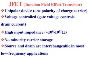
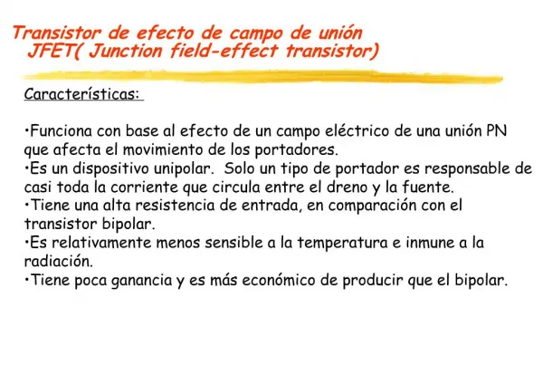
FET = Field Effect Transistor N-channel or P-channel J-FET Bollen
J-FET, OVERVIEW Bollen
JFET vs BJT Bollen
J-FET vs BJT Bollen
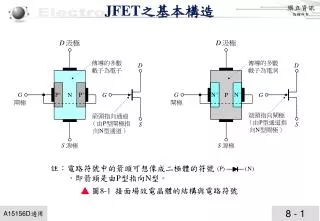
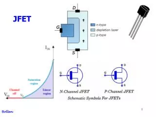
Physical structure There is one PN junction from gate to channel used in REVERSE Bollen
JFET working Bollen
JFET working Bollen
Vp and Idss In data sheet p = pinch-off dss = drain source shorted or saturated = maximum current JFET input parameters Bollen
JFET DC formula Solve with abc formula Bollen
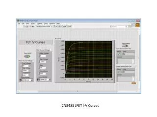
JFET Output parameters Uds < Up = ohmic region, Uds > Up = saturated region Bollen
JFET JFET is not often used in the ohmic (triode) region If so it is used as an variable resistor Bollen
JFET output Bollen
JFET output Bollen
JFET transconductance Bollen
JFET transconductance Bollen
JFET ac parameters Bollen
JFET simulation parameters micro cap VTO Threshold voltage BETA Transconductance parameter Bollen
JFET fixed bias Steady Ugs, no variation possible, so we make the same effect with resistors. U = I . R Now we can vary around the bias point Bollen
JFET self bias Ug = 0 volt, NO gate current Ugs = Ug – Us = 0 – Ids.Rs Rin = 1 Meg Ohm Bollen
JFET self bias Varying Rs = varying the Q-point = operating point Bollen
Ug 0 volt Ugs = Ug – Us = Vg – Ids.Rs, bias is made at GATE and SOURCE JFET voltage divider bias Bollen
Metal Oxide Silicium Field Effect Transistor MOSFET Bollen
MOSFET Bollen
MOSFET Bollen
MOSFET dc Bollen
MOSFET ac Bollen