Download
1 / 11
110 likes | 250 Views
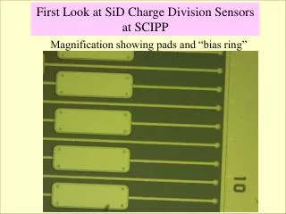
First Look at SiD Charge Division Sensors at SCIPP. Magnification showing pads and “bias ring”. Higher Magnification showing apparent “vias” at regular intervals along length of strip. September 2, 2008 IV and CV curves on Charge Division Sensors Setup: -Backside H.V. (High Pot)

E N D
First Look at SiD Charge Division Sensors at SCIPP Magnification showing pads and “bias ring”
Higher Magnification showing apparent “vias” at regular intervals along length of strip
September 2, 2008 IV and CV curves on Charge Division Sensors Setup: -Backside H.V. (High Pot) -GND (Low Pot) on strip zero, next to bias and guard ring -GND (Low Pot) on Bias Ring, and Strip's 2nd and 5th Neighbor
September 2, 2008 IV and CV curves on Charge Division Sensors Setup: -Backside H.V. (High Pot) -GND (Low Pot) on strip zero, next to bias and guard ring -GND (Low Pot) on Bias Ring, and Strip's 2nd and 5th Neighbor
September 2, 2008 IV and CV curves on Charge Division Sensors Setup: -Backside H.V. (High Pot) -GND (Low Pot) on strip zero, next to bias and guard ring -GND (Low Pot) on Bias Ring, and Strip's 2nd and 5th Neighbor
September 2, 2008 IV and CV curves on Charge Division Sensors Setup: -Backside H.V. (High Pot) -GND (Low Pot) on strip zero, next to bias and guard ring -GND (Low Pot) on Bias Ring, Guard Ring, and 2nd Neighbor
September 2, 2008 IV and CV curves on Charge Division Sensors Setup: -Backside H.V. (High Pot) -GND (Low Pot) on strip zero, next to bias and guard ring -GND (Low Pot) on Bias Ring, Guard Ring, and 2nd Neighbor
September 2, 2008 IV and CV curves on Charge Division Sensors Setup: -Backside H.V. (High Pot) -GND (Low Pot) on strip zero, next to bias and guard ring -GND (Low Pot) on Bias Ring, Guard Ring, and 2nd Neighbor
September 2, 2008 IV and CV curves on Charge Division Sensors Setup: -Backside H.V. (High Pot) -GND (Low Pot) on strip zero, next to bias and guard ring -GND (Low Pot) on Bias Ring, and Strip's 1st Neighbor
September 2, 2008 IV and CV curves on Charge Division Sensors Setup: -Backside H.V. (High Pot) -GND (Low Pot) on strip zero, next to bias and guard ring -GND (Low Pot) on Bias Ring, and Strip's 1st Neighbor
September 2, 2008 IV and CV curves on Charge Division Sensors Setup: -Backside H.V. (High Pot) -GND (Low Pot) on strip zero, next to bias and guard ring -GND (Low Pot) on Bias Ring, and Strip's 1st Neighbor