Download
1 / 44
570 likes | 1.31k Views
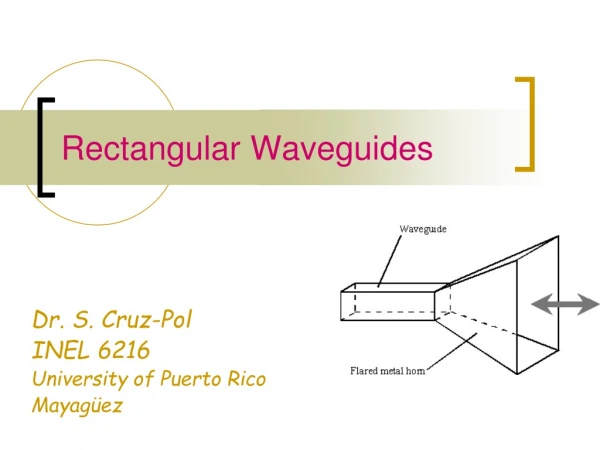
Waveguides. Dr. S. Cruz-Pol INEL 4152 University of Puerto Rico Mayag ü ez. Waveguide components. Waveguide to coax adapter. Rectangular waveguide. Waveguide bends. E-tee. Figures from: www.microwaves101.com/encyclopedia/waveguide.cfm. More waveguides.

E N D
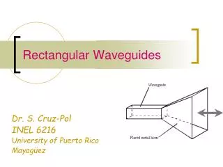
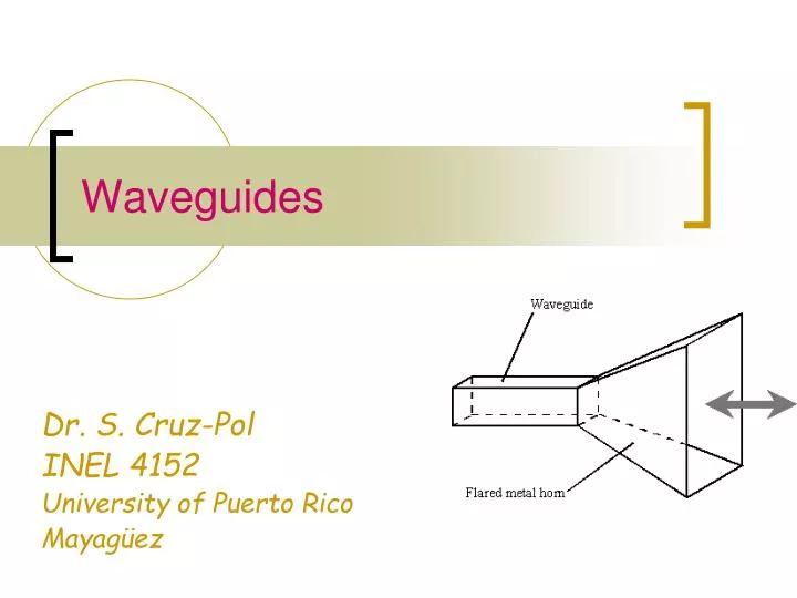
Waveguides Dr. S. Cruz-Pol INEL 4152 University of Puerto Rico Mayagüez
Waveguide components Waveguide to coax adapter Rectangular waveguide Waveguide bends E-tee Figures from: www.microwaves101.com/encyclopedia/waveguide.cfm
More waveguides http://www.tallguide.com/Waveguidelinearity.html
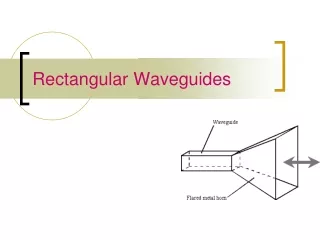
Uses • To reduce attenuation loss • @ High frequencies • @ High power • Can operate only above certain frequencies • Act as a High-pass filter • Normally circular or rectangular • We will assume lossless rectangular
Rectangular WG • Need to find the fields components of the em wave inside the waveguide • Ez Hz Ex Hx Ey Hy • We’ll find that waveguidesdon’t support TEM waves http://www.ee.surrey.ac.uk/Personal/D.Jefferies/wguide.html
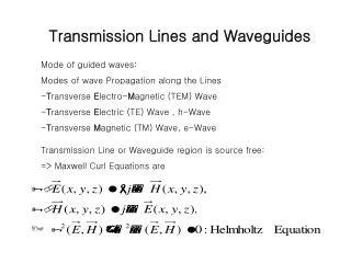
Rectangular Waveguides: Fields inside Using phasors & assuming waveguide filled with • lossless dielectric material and • walls of perfect conductor, the wave inside should obey…
Other components From Faraday and Ampere Laws we can find the remaining four components: *So once we know Ezand Hz, we can find all the other fields.
Modes of propagation From these equations we can conclude: • TEM (Ez=Hz=0) can’t propagate. • TE (Ez=0) transverse electric • In TE mode, the electric lines of flux are perpendicular to the axis of the waveguide • TM (Hz=0) transverse magnetic, Ezexists • In TM mode, the magnetic lines of flux are perpendicular to the axis of the waveguide. • HE hybrid modes in which all components exists
TM Mode • Boundary conditions: From these, we conclude: X(x) is in the form of sin kxx, where kx=mp/a, m=1,2,3,… Y(y) is in the form of sin kyy, where ky=np/b,n=1,2,3,… So the solution for Ez(x,y,z) is Figure from: www.ee.bilkent.edu.tr/~microwave/programs/magnetic/rect/info.htm
TM Mode • Substituting
TMmn • Other components are
TM modes • The m and n represent the mode of propagation and indicates the number of variations of the field in the x and y directions • Note that for the TM mode, if n or m =0, all fields are =0. • See applet by Paul Falstad http://www.falstad.com/embox/guide.html
TM Cutoff • The cutoff frequency occurs when • Evanescent: • Means no propagation, everything is attenuated • Propagation: • This is the case we are interested since is when the wave is allowed to travel through the guide.
Cutoff attenuation Propagation of mode mn fc,mn • The cutoff frequency is the frequency below which attenuation occurs and above which propagation takes place. (High Pass) • The phase constant becomes
Phase velocity and impedance • The phase velocity is defined as • And the intrinsic impedance of the mode is
Ez m = 1 m = 2 m = 3 z a x Related example of how fields look: Parallel plate waveguide - TM modes 0 a x
TE Mode • Boundary conditions: From these, we conclude: X(x) is in the form of cos kxx, where kx=mp/a, m=0,1,2,3,… Y(y) is in the form of cos kyy, where ky=np/b,n=0,1,2,3,… So the solution for Ez(x,y,z) is Figure from: www.ee.bilkent.edu.tr/~microwave/programs/magnetic/rect/info.htm
TE Mode • Substituting • Note that n and m cannot be both zero because the fields will all be zero. • But either ONE of them can be =0
TEmn • Other components are
Cutoff attenuation Propagation of mode mn fc,mn • The cutoff frequency is the same expression as for the TM mode • But the lowest attainable frequencies are lowest because here n or m can be zero.
Dominant Mode • The dominant mode is the mode with lowest cutoff frequency. • It’s always TE10 • The order of the next modes change depending on the dimensions of the waveguide.
Variation of wave impedance • Wave impedance varies with frequency and mode h hTE h’ hTM 0 fc,mn
Example 1: Consider a length of air-filled copper X-band waveguide, with dimensions a=2.286cm, b=1.016cm operating at 10GHz. Find the cutoff frequencies of all possible propagating modes. Solution: • From the formula for the cut-off frequency
Example 2 An air-filled 5-by 2-cm waveguide has at 15GHz • What mode is being propagated? • Find b • Determine Ey/Ex
Group velocity, ug • Is the velocity at which the energy travels. • It is always less than u’ http://www.tpub.com/content/et/14092/css/14092_71.htm
Group Velocity • As frequency is increased, the group velocity increases.
Power transmission • The average Poynting vector for the waveguide fields is • where h = hTE or hTM depending on the mode [W/m2] [W]
Attenuation in Lossy waveguide • When dielectric inside guide is lossy, and walls are not perfect conductors, power is lost as it travels along guide. • The loss power is • Where a=ac+ad are the attenuation due to ohmic (conduction) and dielectric losses • Usually ac >> ad
Attenuation for TE10 • Dielectric attenuation, Np/m • Conductor attenuation, Np/m Dielectric conductivity!
Waveguide Cavities • Cavities, or resonators, are used for storing energy • Used in klystron tubes, band-pass filters and frequency meters • It’s equivalent to a RLC circuit at high frequency • Their shape is that of a cavity, either cylindrical or cubical.
TMmnp Boundary Conditions From these, we conclude: kx=mp/a ky=np/b kz=pp/c where c is the dimension in z-axis c
Resonant frequency • The resonant frequency is the same for TM or TE modes, except that the lowest-order TM is TM110 and the lowest-order in TE is TE101.
TEmnp Boundary Conditions From these, we conclude: kx=mp/a ky=np/b kz=pp/c where c is the dimension in z-axis c
Quality Factor, Q • The cavity has walls with finite conductivity and is therefore losing stored energy. • The quality factor, Q, characterized the loss and also the bandwidth of the cavity resonator. • Dielectric cavities are used for resonators, amplifiers and oscillators at microwave frequencies.
A dielectric resonator antenna with a cap for measuring the radiation efficiency Univ. of Mississippi
Quality Factor, Q • Is defined as
Example For a cavity of dimensions; 3cm x 2cm x 7cm filled with air and made of copper (sc=5.8 x 10⁷) • Find the resonant frequency and the quality factor for the dominant mode. Answer: