Download
1 / 21
420 likes | 1.19k Views
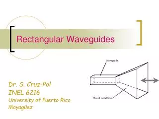
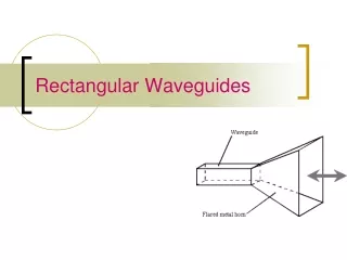
Waveguides. 1. Figure 12.1 Typical waveguides. Figure 12.2 A rectangular waveguide with perfectly conducting walls, filled with a lossless material. Figure 12.3 Components of EM fields in a rectangular waveguide: (a) TE mode E z = 0, (b ) TM mode, H z = 0.

E N D
Figure 12.1 Typical waveguides. Elements of Electromagnetics Fourth Edition Sadiku
Figure 12.2 A rectangular waveguide with perfectly conducting walls, filled with a lossless material. Elements of Electromagnetics Fourth Edition Sadiku
Figure 12.3 Components of EM fields in a rectangular waveguide: (a) TE mode Ez= 0, (b) TM mode, Hz= 0. Elements of Electromagnetics Fourth Edition Sadiku
Figure 12.4 Field configuration for TM21 mode. Elements of Electromagnetics Fourth Edition Sadiku
Figure 12.5 Field configuration for TE32 mode. Elements of Electromagnetics Fourth Edition Sadiku
Figure 12.6 Variation of wave impedance with frequency for TE and TM modes. Elements of Electromagnetics Fourth Edition Sadiku
Figure 12.7 Variation of the field components with x for TE10 mode. Elements of Electromagnetics Fourth Edition Sadiku
Figure 12.8 Field lines for TE10 mode, corresponding to components (a), (b), and (c) in Figure 12.7. Elements of Electromagnetics Fourth Edition Sadiku
Figure 12.9 Cutoff frequencies of rectangular waveguide with a=2.5b; for Example 12.1. Elements of Electromagnetics Fourth Edition Sadiku
Figure 12.10 (a) Decomposition of TE10 made into two plane waves.(b) Relationship between u¢, up, and ug. Elements of Electromagnetics Fourth Edition Sadiku
Figure 12.11 Surface current on guide walls for TE10 mode. Elements of Electromagnetics Fourth Edition Sadiku
Figure 12.12 Excitation of modes in a rectangular waveguide: (a) TE10 mode, (b) TM11 mode. Elements of Electromagnetics Fourth Edition Sadiku
Figure 12.13 Field lines for TM11 mode; for Example 12.7. Elements of Electromagnetics Fourth Edition Sadiku
Figure 12.14 Field lines for TE11 mode; for Practice Exercise 12.7. Elements of Electromagnetics Fourth Edition Sadiku
Figure 12.15 Rectangular cavity. Elements of Electromagnetics Fourth Edition Sadiku
Figure 12.16 Optical fiber. Elements of Electromagnetics Fourth Edition Sadiku
Figure 12.17 (a) multimode, (b) multimode graded index, (c) single mode. Optical fiber transmission modes. (From W. Stallings, Local and Metropolitan Area Networks, 4th ed. New York: Macmillan, 1993, p. 85.) Elements of Electromagnetics Fourth Edition Sadiku
Figure 12.18 A typical fiber-optic system. Elements of Electromagnetics Fourth Edition Sadiku
Figure 12.19 Numerical aperture and acceptance angle. Elements of Electromagnetics Fourth Edition Sadiku
Figure 12.20 For Problem 12.18. Elements of Electromagnetics Fourth Edition Sadiku