Download

1 / 66
660 likes | 832 Views
CPSC 614:Graduate Computer Architecture Lecture 2 Pipelining, Caching, and Benchmarks. Prof. Lawrence Rauchwerger. MEM/WB. ID/EX. EX/MEM. IF/ID. Adder. 4. Address. ALU. 5 Steps of MIPS Datapath. Instruction Fetch. Execute Addr. Calc. Memory Access. Instr. Decode Reg. Fetch.

E N D
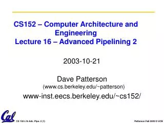
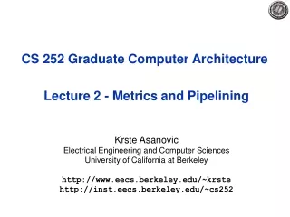
CPSC 614:Graduate Computer ArchitectureLecture 2 Pipelining, Caching, and Benchmarks Prof. Lawrence Rauchwerger
MEM/WB ID/EX EX/MEM IF/ID Adder 4 Address ALU 5 Steps of MIPS Datapath Instruction Fetch Execute Addr. Calc Memory Access Instr. Decode Reg. Fetch Write Back Next PC MUX Next SEQ PC Next SEQ PC Zero? RS1 Reg File MUX Memory RS2 Memory MUX MUX Sign Extend WB Data Imm Datapath RD RD RD Control Path
MEM/WB ID/EX EX/MEM IF/ID Adder 4 Address ALU Inst 2 Inst 3 Inst 1 Inst 2 Inst 1 5 Steps of MIPS Datapath Instruction Fetch Execute Addr. Calc Memory Access Instr. Decode Reg. Fetch Write Back Next PC MUX Next SEQ PC Next SEQ PC Zero? RS1 Reg File MUX Memory RS2 Memory MUX MUX Sign Extend Inst 1 WB Data Imm Datapath RD RD RD Control Path
Reg Reg Reg Reg Reg Reg Reg Reg Ifetch Ifetch Ifetch Ifetch DMem DMem DMem DMem ALU ALU ALU ALU Cycle 1 Cycle 2 Cycle 3 Cycle 4 Cycle 5 Cycle 6 Cycle 7 Review: Visualizing PipeliningFigure 3.3, Page 133 , CA:AQA 2e Time (clock cycles) I n s t r. O r d e r
Limits to pipelining • Hazards: circumstances that would cause incorrect execution if next instruction were launched • Structural hazards: Attempting to use the same hardware to do two different things at the same time • Data hazards: Instruction depends on result of prior instruction still in the pipeline • Control hazards: Caused by delay between the fetching of instructions and decisions about changes in control flow (branches and jumps).
Reg Reg Reg Reg Reg Reg Reg Reg Ifetch Ifetch Ifetch DMem DMem DMem ALU ALU ALU ALU DMem Ifetch Structural Hazard Example: One Memory Port/Structural HazardFigure 3.6, Page 142 , CA:AQA 2e Time (clock cycles) Cycle 1 Cycle 2 Cycle 3 Cycle 4 Cycle 5 Cycle 6 Cycle 7 I n s t r. O r d e r Load DMem Instr 1 Instr 2 Instr 3 Instr 4
Resolving structural hazards • Defn: attempt to use same hardware for two different things at the same time • Solution 1: Wait • must detect the hazard • must have mechanism to stall • Solution 2: Throw more hardware at the problem
Reg Reg Reg Reg Reg Reg Reg Reg Ifetch Ifetch Ifetch Ifetch DMem DMem DMem ALU ALU ALU ALU Bubble Bubble Bubble Bubble Bubble Detecting and Resolving Structural Hazard Time (clock cycles) Cycle 1 Cycle 2 Cycle 3 Cycle 4 Cycle 5 Cycle 6 Cycle 7 I n s t r. O r d e r Load DMem Instr 1 Instr 2 Stall Instr 3
MEM/WB ID/EX EX/MEM IF/ID Adder 4 Address ALU Eliminating Structural Hazards at Design Time Next PC MUX Next SEQ PC Next SEQ PC Zero? RS1 Reg File MUX Instr Cache RS2 Data Cache MUX MUX Sign Extend WB Data Imm Datapath RD RD RD Control Path
Role of Instruction Set Design in Structural Hazard Resolution • Simple to determine the sequence of resources used by an instruction • opcode tells it all • Uniformity in the resource usage • Compare MIPS to IA32? • MIPS approach => all instructions flow through same 5-stage pipeling
Reg Reg Reg Reg Reg Reg Reg Reg Reg Reg ALU ALU ALU ALU ALU Ifetch Ifetch Ifetch Ifetch Ifetch DMem DMem DMem DMem DMem EX WB MEM IF ID/RF I n s t r. O r d e r add r1,r2,r3 sub r4,r1,r3 and r6,r1,r7 or r8,r1,r9 xor r10,r1,r11 Data HazardsFigure 3.9, page 147 , CA:AQA 2e Time (clock cycles)
Three Generic Data Hazards • Read After Write (RAW)InstrJ tries to read operand before InstrI writes it • Caused by a “Data Dependence” (in compiler nomenclature). This hazard results from an actual need for communication. I: add r1,r2,r3 J: sub r4,r1,r3
I: sub r4,r1,r3 J: add r1,r2,r3 K: mul r6,r1,r7 Three Generic Data Hazards • Write After Read (WAR)InstrJ writes operand before InstrI reads it • Called an “anti-dependence” by compiler writers.This results from reuse of the name “r1”. • Can’t happen in MIPS 5 stage pipeline because: • All instructions take 5 stages, and • Reads are always in stage 2, and • Writes are always in stage 5
I: sub r1,r4,r3 J: add r1,r2,r3 K: mul r6,r1,r7 Three Generic Data Hazards • Write After Write (WAW)InstrJ writes operand before InstrI writes it. • Called an “output dependence” by compiler writersThis also results from the reuse of name “r1”. • Can’t happen in MIPS 5 stage pipeline because: • All instructions take 5 stages, and • Writes are always in stage 5 • Will see WAR and WAW in later more complicated pipes
Reg Reg Reg Reg Reg Reg Reg Reg Reg Reg ALU ALU ALU ALU ALU Ifetch Ifetch Ifetch Ifetch Ifetch DMem DMem DMem DMem DMem I n s t r. O r d e r add r1,r2,r3 sub r4,r1,r3 and r6,r1,r7 or r8,r1,r9 xor r10,r1,r11 Forwarding to Avoid Data HazardFigure 3.10, Page 149 , CA:AQA 2e Time (clock cycles)
ALU HW Change for ForwardingFigure 3.20, Page 161, CA:AQA 2e ID/EX EX/MEM MEM/WR NextPC mux Registers Data Memory mux mux Immediate
Reg Reg Reg Reg Reg Reg Reg Reg ALU Ifetch Ifetch Ifetch Ifetch DMem DMem DMem DMem ALU ALU ALU lwr1, 0(r2) I n s t r. O r d e r sub r4,r1,r6 and r6,r1,r7 or r8,r1,r9 Data Hazard Even with ForwardingFigure 3.12, Page 153 , CA:AQA 2e Time (clock cycles)
Resolving this load hazard • Adding hardware? ... not • Detection? • Compilation techniques? • What is the cost of load delays?
Reg Reg Reg Ifetch Ifetch Ifetch Ifetch DMem ALU Bubble ALU ALU Reg Reg DMem DMem Bubble Reg Reg Resolving the Load Data Hazard Time (clock cycles) I n s t r. O r d e r lwr1, 0(r2) sub r4,r1,r6 and r6,r1,r7 Bubble ALU DMem or r8,r1,r9 How is this different from the instruction issue stall?
Software Scheduling to Avoid Load Hazards Try producing fast code for a = b + c; d = e – f; assuming a, b, c, d ,e, and f in memory. Slow code: LW Rb,b LW Rc,c ADD Ra,Rb,Rc SW a,Ra LW Re,e LW Rf,f SUB Rd,Re,Rf SW d,Rd Fast code: LW Rb,b LW Rc,c LW Re,e ADD Ra,Rb,Rc LW Rf,f SW a,Ra SUB Rd,Re,Rf SW d,Rd
Instruction Set Connection • What is exposed about this organizational hazard in the instruction set? • k cycle delay? • bad, CPI is not part of ISA • k instruction slot delay • load should not be followed by use of the value in the next k instructions • Nothing, but code can reduce run-time delays • MIPS did the transformation in the assembler
User program plus Data this can change! Main Memory ADD SUB AND . . . one of these is mapped into one of these DATA execution unit CPU control memory Historical Perspective: Microprogramming Supported complex instructions a sequence of simple micro-inst (RTs) Pipelined micro-instruction processing, but very limited view. Could not reorganize macroinstructions to enable pipelining
Administration • Tuesday is Stack vs GPR Debate • Christine Chevalier Dan Adkins • Yury Markovskiy Mukund Seshadri • Yatish Patel Manikandan Narayanan • Rachael Rubin Hayley Iben • Think about address size, code density, performance, compilation techniques, design complexity, program characteristics • Prereq quiz afterwards • Please register (form on page)
Reg Reg Reg Reg Reg Reg Reg Reg Reg Reg ALU ALU ALU ALU ALU Ifetch Ifetch Ifetch Ifetch Ifetch DMem DMem DMem DMem DMem 10: beq r1,r3,36 14: and r2,r3,r5 18: or r6,r1,r7 22: add r8,r1,r9 36: xor r10,r1,r11 Control Hazard on Branches=> Three Stage Stall
Example: Branch Stall Impact • If 30% branch, Stall 3 cycles significant • Two part solution: • Determine branch taken or not sooner, AND • Compute taken branch address earlier • MIPS branch tests if register = 0 or 0 • MIPS Solution: • Move Zero test to ID/RF stage • Adder to calculate new PC in ID/RF stage • 1 clock cycle penalty for branch versus 3
MEM/WB ID/EX EX/MEM IF/ID Adder 4 Address ALU Pipelined MIPS DatapathFigure 3.22, page 163, CA:AQA 2/e Instruction Fetch Execute Addr. Calc Memory Access Instr. Decode Reg. Fetch Write Back Next SEQ PC Next PC MUX Adder Zero? RS1 Reg File Memory RS2 Data Memory MUX MUX Sign Extend WB Data Imm RD RD RD • Data stationary control • local decode for each instruction phase / pipeline stage
Four Branch Hazard Alternatives #1: Stall until branch direction is clear #2: Predict Branch Not Taken • Execute successor instructions in sequence • “Squash” instructions in pipeline if branch actually taken • Advantage of late pipeline state update • 47% MIPS branches not taken on average • PC+4 already calculated, so use it to get next instruction #3: Predict Branch Taken • 53% MIPS branches taken on average • But haven’t calculated branch target address in MIPS • MIPS still incurs 1 cycle branch penalty • Other machines: branch target known before outcome
Four Branch Hazard Alternatives #4: Delayed Branch • Define branch to take place AFTER a following instruction branch instructionsequential successor1 sequential successor2 ........ sequential successorn ........ branch target if taken • 1 slot delay allows proper decision and branch target address in 5 stage pipeline • MIPS uses this Branch delay of length n
Delayed Branch • Where to get instructions to fill branch delay slot? • Before branch instruction • From the target address: only valuable when branch taken • From fall through: only valuable when branch not taken • Canceling branches allow more slots to be filled • Compiler effectiveness for single branch delay slot: • Fills about 60% of branch delay slots • About 80% of instructions executed in branch delay slots useful in computation • About 50% (60% x 80%) of slots usefully filled • Delayed Branch downside: 7-8 stage pipelines, multiple instructions issued per clock (superscalar)
Recall:Speed Up Equation for Pipelining For simple RISC pipeline, CPI = 1:
Example: Evaluating Branch Alternatives Assume: Conditional & Unconditional = 14%, 65% change PC Scheduling Branch CPI speedup v. scheme penalty stall Stall pipeline 3 1.42 1.0 Predict taken 1 1.14 1.26 Predict not taken 1 1.09 1.29 Delayed branch 0.5 1.07 1.31
The Memory Abstraction • Association of <name, value> pairs • typically named as byte addresses • often values aligned on multiples of size • Sequence of Reads and Writes • Write binds a value to an address • Read of addr returns most recently written value bound to that address command (R/W) address (name) data (W) data (R) done
MEM/WB ID/EX EX/MEM IF/ID Adder 4 Address ALU Relationship of Caches and Pipeline Memory D-$ I-$ Next SEQ PC Next PC MUX Adder Zero? RS1 Reg File RS2 Memory Data Memory MUX WB Data MUX Sign Extend Imm RD RD RD
Example: Dual-port vs. Single-port • Machine A: Dual ported memory • Machine B: Single ported memory, but its pipelined implementation has a 1.05 times faster clock rate • Ideal CPI = 1 for both • Loads are 40% of instructions executed • Speedup(enhancement) = Time w/o enhancement / Time w/ • Speedup(B) = Time(A) / Time(B) = CPI(A)xCT(A) / CPI(B)xCT(B) = 1 / (1.4 x 1/1.05) = 0.75 Machine A is 1.33 times faster
Lower Level Memory Upper Level Memory To Processor Blk X From Processor Blk Y Memory Hierarchy: Terminology • Hit: data appears in some block in the upper level (example: Block X) • Hit Rate: the fraction of memory access found in the upper level • Hit Time: Time to access the upper level which consists of RAM access time + Time to determine hit/miss • Miss: data needs to be retrieve from a block in the lower level (Block Y) • Miss Rate = 1 - (Hit Rate) • Miss Penalty: Time to replace a block in the upper level + Time to deliver the block the processor • Hit Time << Miss Penalty (500 instructions on 21264!)
4 Questions for Memory Hierarchy • Q1: Where can a block be placed in the upper level? (Block placement) • Q2: How is a block found if it is in the upper level? (Block identification) • Q3: Which block should be replaced on a miss? (Block replacement) • Q4: What happens on a write? (Write strategy)
Simplest Cache: Direct Mapped Memory Address Memory 0 4 Byte Direct Mapped Cache 1 Cache Index 2 • Location 0 can be occupied by data from: • Memory location 0, 4, 8, ... etc. • In general: any memory locationwhose 2 LSBs of the address are 0s • Address<1:0> => cache index • Which one should we place in the cache? • How can we tell which one is in the cache? 0 3 1 4 2 5 3 6 7 8 9 A B C D E F
1 KB Direct Mapped Cache, 32B blocks • For a 2 ** N byte cache: • The uppermost (32 - N) bits are always the Cache Tag • The lowest M bits are the Byte Select (Block Size = 2 ** M) 31 9 4 0 Cache Tag Example: 0x50 Cache Index Byte Select Ex: 0x01 Ex: 0x00 Stored as part of the cache “state” Valid Bit Cache Tag Cache Data : Byte 31 Byte 1 Byte 0 0 : 0x50 Byte 63 Byte 33 Byte 32 1 2 3 : : : : Byte 1023 Byte 992 31
Cache Data Cache Tag Valid Cache Block 0 : : : Compare Two-way Set Associative Cache • N-way set associative: N entries for each Cache Index • N direct mapped caches operates in parallel (N typically 2 to 4) • Example: Two-way set associative cache • Cache Index selects a “set” from the cache • The two tags in the set are compared in parallel • Data is selected based on the tag result Cache Index Valid Cache Tag Cache Data Cache Block 0 : : : Adr Tag Compare 1 0 Mux Sel1 Sel0 OR Cache Block Hit
Cache Index Valid Cache Tag Cache Data Cache Data Cache Tag Valid Cache Block 0 Cache Block 0 : : : : : : Adr Tag Compare Compare 1 0 Mux Sel1 Sel0 OR Cache Block Hit Disadvantage of Set Associative Cache • N-way Set Associative Cache v. Direct Mapped Cache: • N comparators vs. 1 • Extra MUX delay for the data • Data comes AFTER Hit/Miss • In a direct mapped cache, Cache Block is available BEFORE Hit/Miss: • Possible to assume a hit and continue. Recover later if miss.
01234567 01234567 01234567 1111111111222222222233 01234567890123456789012345678901 Q1: Where can a block be placed in the upper level? • Block 12 placed in 8 block cache: • Fully associative, direct mapped, 2-way set associative • S.A. Mapping = Block Number Modulo Number Sets Direct Mapped (12 mod 8) = 4 2-Way Assoc (12 mod 4) = 0 Full Mapped Cache Memory
Block Address Block Offset Tag Index Q2: How is a block found if it is in the upper level? • Tag on each block • No need to check index or block offset • Increasing associativity shrinks index, expands tag
Q3: Which block should be replaced on a miss? • Easy for Direct Mapped • Set Associative or Fully Associative: • Random • LRU (Least Recently Used) Assoc: 2-way 4-way 8-way Size LRU Ran LRU Ran LRU Ran 16 KB 5.2% 5.7% 4.7% 5.3% 4.4% 5.0% 64 KB 1.9% 2.0% 1.5% 1.7% 1.4% 1.5% 256 KB 1.15% 1.17% 1.13% 1.13% 1.12% 1.12%
Q4: What happens on a write? • Write through—The information is written to both the block in the cache and to the block in the lower-level memory. • Write back—The information is written only to the block in the cache. The modified cache block is written to main memory only when it is replaced. • is block clean or dirty? • Pros and Cons of each? • WT: read misses cannot result in writes • WB: no repeated writes to same location • WT always combined with write buffers so that don’t wait for lower level memory
Cache Processor DRAM Write Buffer Write Buffer for Write Through • A Write Buffer is needed between the Cache and Memory • Processor: writes data into the cache and the write buffer • Memory controller: write contents of the buffer to memory • Write buffer is just a FIFO: • Typical number of entries: 4 • Works fine if: Store frequency (w.r.t. time) << 1 / DRAM write cycle • Memory system design: • Store frequency (w.r.t. time) -> 1 / DRAM write cycle • Write buffer saturation
Processor Control Tertiary Storage (Disk/Tape) Secondary Storage (Disk) Second Level Cache (SRAM) Main Memory (DRAM) On-Chip Cache Datapath Registers Speed (ns): 1s 10s 100s 10,000,000s (10s ms) 10,000,000,000s (10s sec) Size (bytes): 100s Ks Ms Gs Ts A Modern Memory Hierarchy • By taking advantage of the principle of locality: • Present the user with as much memory as is available in the cheapest technology. • Provide access at the speed offered by the fastest technology.
size of information blocks that are transferred from secondary to main storage (M) block of information brought into M, and M is full, then some region of M must be released to make room for the new block --> replacement policy which region of M is to hold the new block --> placement policy missing item fetched from secondary memory only on the occurrence of a fault --> demand load policy disk mem cache reg pages frame Basic Issues in VM System Design Paging Organization virtual and physical address space partitioned into blocks of equal size page frames pages
V = {0, 1, . . . , n - 1} virtual address space M = {0, 1, . . . , m - 1} physical address space MAP: V --> M U {0} address mapping function Address Map n > m MAP(a) = a' if data at virtual address a is present in physical address a' and a' in M = 0 if data at virtual address a is not present in M a missing item fault Name Space V fault handler Processor 0 Secondary Memory Addr Trans Mechanism Main Memory a a' physical address OS performs this transfer
Implications of Virtual Memory for Pipeline design • Fault? • Address translation?
V.A. P.A. Paging Organization unit of mapping 0 frame 0 1K Addr Trans MAP 0 1K page 0 1024 1 1K 1024 1 1K also unit of transfer from virtual to physical memory 7 1K 7168 Physical Memory 31 1K 31744 Virtual Memory Address Mapping 10 VA page no. disp Page Table Page Table Base Reg Access Rights actually, concatenation is more likely V + PA index into page table table located in physical memory physical memory address