Download
1 / 31
320 likes | 723 Views
Soft Matter Sample Environment at ISIS, from inception to fruition and beyond, with continuous evaluation and improvement. Polymers. Proteins. Andy Church Manager of Soft Matter TS1 and TS2 ISIS Facility, STFC ICANSXXIII, Chattanooga, TN, USA 14 th_ 18 th October 2019. DNA.

E N D
Soft Matter Sample Environment at ISIS, from inception to fruition and beyond, with continuous evaluation and improvement. Polymers Proteins Andy Church Manager ofSoft Matter TS1 and TS2 ISIS Facility, STFC ICANSXXIII, Chattanooga, TN, USA 14th_18th October 2019 DNA
Today’s Schedule of Events.…. Quick overview of progress Beamlines now being supported SE and Scientist’s working together A bit of ‘science stuff’……from actual experiments with data Furnace Multi sample changer Chromatography flow cell Humidity chamber Helium Flow cryostat
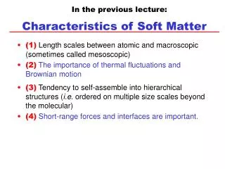
What we are dealing with.…. A lipid is chemically defined as a substance that is insoluble in water and soluble in alcohol, ether, and chloroform. Lipids are an important component of living cells. Together with carbohydrates and proteins, lipids are the main constituents of plant and animal cells. Cholesterol and triglycerides are lipids. Neutron scattering is an excellent and unique probe for membrane structure and dynamics
The VeryBeginning. • Infrastructure…… • November 2011
Present Day… • Infrastructure…… • Have the right Lab area • Have the right Lab furniture • Have correct tools you need for the task Target Station 1 Hall. Target Station 2 Hall.
Present Day… • Infrastructure…… • Got a ‘dirty’ bench area • Racking for beam line specific kit • Dedicated Laser room for DLS to compliment SANS measurements
Present Day… • Infrastructure…… • Extended Storage Area
The Future… • Infrastructure…… • New TS2 Lab, situated on level 1 • Three times the size • Close to the biolab • Near to goods lift • East side where LSS beam lines are
Soft Matter is happening mostly on small angle scattering and reflectometry beam lines. At ISIS this will be: • LOQ • CRISP • SURF • SANS2D • INTER • OFFSPEC • POLREF • LARMOR • ZOOM • Plus recently IRIS, IMAT and SANDALS
Furnace on POLREF Old setup New setup • 1 x 10⁻⁶ vacuum from a standard Turbo pump. • 25C to 400C temperature range. • Very stable temperature +/-0.1C. • Fits in standard GMW 3473 magnet • Demand for a close to room temperature (up to 300C) vacuum furnace for device applications
Furnace New setup • Outgases a lot, depositing a film of something on windows and sample. Requires a prebake before use to avoid this • Need 0C – 1200C or even 0C-1500C temperature range for a full science program. Looking at optical furnace design. • Cartridge heaters can generate a magnetic field that can depolarise a polarised neutron beam, and be bad for magnetic measurements. • Optical furnace would avoids this.
Results Obtained • Example: FeRh alloy meta magnetic material. This has a low temperature antiferromagnetic(AF) and a high temperature (100C) ferromagnetic (F) state. • FeRh is of interest as it can be used to make a magnetic fridge as the AF to F transition has a large entropy change. It can also be used to make Heat assisted read right media (HARRM) for hard disks in computers, allowing more data to be stored. • Work between beam line scientists and the SM staff allowed this current version to happen and producing science. • Magnetism changing with function of temperature
Furnace, next steps • Up to 1000°C • 10, 15 and 20mm samples • Minimum material in beam • 2 vanadium shields • 40° C outer shireld, offline tests • Gold plated 150W halogen lamps • To fit in 80mm sample space • Flowing under argon atmosphere
Multi Sample Changer • Sits in GMW • Allows up to 6 samples to be mounted and measured in in sequence. • Excellent for experiments with large numbers of samples. Eg materials studies where growth parameters are changed etc. • Example High entropy alloys grown using different gas pressures, in this case a quintary alloy (5 components). • This is of interest as magnetic materials are needed that can be used for thermal electric contacts. But they need to be able to survive in chemically corrosive and high temperature environments like in a catalytic converter. HEA’s are able to do this. • Reduce neutron noise, raised pucks
Multi Sample Changer • This is allows us to align up 6 samples and leave the beamline running for a 24 or 48 hour period, freeing staff up from night shifts and weekends. • Few issues of sample mounts bending, corrected with dumbbell supports. Thin film coating technology, example in engines, brake pads, turbine blades, used to generate power from waste heat. Optimise the magnetic properties The magnetic differences between the pristine (Vacuum) and full Argon pressure grown cases of the HEA. Looking to optimise the magnetic properties
SANS Chromatography Flow Cell. • Users wanted to look inside this resin/ porous bead. • Structural Studies on Therapeutic Protein Purification • Neutrons are the only technique that can do this • Scientists from UCL, University of Delaware, NCNR at NIST and ISIS • Immunoglobulins are proteins from the immune system and can be used to treat individuals who have a impaired immune system. • To enable this research SM developed a quartz flow cell chromatography column. Lab sized Protein-a columns Industrial Protein-a columns
SANS Chromatography Flow Cell. • 3D printed Ali/ ASA • Cut outs for reduced cost/ time and price • Pre-beam testing in lab • Quartz windows • 2mm path length • Bad Flow • Porous
SANS Chromatography Flow Cell. Custom-made quartz flow through cell The 1ml chamber (50mm x 8mm x 1mm) in the middle of the cell is packed with resin. Measurements were performed at three different positions of the cell (top, middle and bottom all evenly spaced between them) since the antibody concentration differs across the column. This column is built to closely resemble the real life chromatographic columns.
SANS Chromatography Flow Cell. In situ on SANS2D Inflow from HPLC OmniFit containing Filter #1 1.0 × 8 × 50 mm Flow cell filled with chromatography resin. Solution mixing controlled by HPLC pumps OmniFit containing Filter #2 Outflow to waste
SANS Chromatography Flow Cell. • Latest design • For treating aggressive cancers • Chemicals very difficult to make and highly expensive….. • Over time columns foul and degrade with a build up of protein, and have to be replaced…expensive Length scales involved in the affinity chromatography. A. SEM of an individual silica bead with size 60μm, B. Close-up of the silica bead surface showing the pores of an average size of 100nm, C. Single silica bead pore coated with IgG molecules with an average of 4.2nm distance between the antibody molecules.
SANS Chromatography Flow Cell. The experimental data gathered from different scattering vector ranges (Q). A. on the left-hand side is the low Q regime. The blue line indicates no IgG present in the system with a peak at 0.0048Å. The purple line shows the data after the addition of 69mg of IgG into the system, which gives rise to two peaks at 0.0048Å and 0.0098Å (128nm and 66nm in real space respectively). The SEM image on top of the data shows what the two peaks might correspond to in real life (pore size and pore to pore correlation respectively). B. on the right-hand side is the higher Q regime taken after the addition of 50mg of IgG into the cell. At 0.052Å (6nm) a third peak is visible. On top of the data is an IgG molecule schematic, showing what the 4.2nm corresponding in-plane repeat of IGg bound onto the resin surface.
Humidity Cell • Range of 20-80% • Using known salts, 11-93% • Options: flow gas, cooling, heating • Humidity sensor/ temp • Kinematic mounting • Gas tight
Humidity Cell • OFFSPEC beam line • Actual experiment • Structures of polymer electrolyte membranes and binders and the distribution of water inside arevery important when designing new ion-conductive ionomers for polymer electrolyte fuel cells • For fuel cell applications it is important to understand how the water distributes itself within the polymer film, and how additives in the polymer affect this.
Humidity Cell • Neutron reflectivity is perfectly suited for studying this, but for the experiment to be successful we need to carefully control the temperature or humidity of the polymer...
Little Blue Cryostat • Stability and thermalisation: • Temperature stable with +/-0.01K for very long time periods. Ideal for neutrons. • Exchange gas gives good uniform thermalisation over the whole sample when at temperature. • Ideal for large parametric studies, with many samples: • Rapid sample changes. • Rapid cool down and warmup times. • Optical access, allowing laser alignment hence significantly faster sample alignments.
Little Blue Cryostat • Allows highly modifiable sample sticks and holders: • Low noise (neutron background) Aluminum annulus holders. • Sample stick allows lots of electrical connections for thermal couples (little blue has 3) and electrical measurements. • Can make as many sticks as you like high E field, Rotation, etc • Magnetic compatibility: • Has low stray magnetic fields. Ideal for low and high field polarised neutron work. • Compatibly with off the shelf GMW magnets etc.
Little Blue Cryostat • Better Polarised neutron transport via the removal of large amounts of ferrous material in the cryostat sample stick and tail. ie. mounting plates, screws, nuts and bolts • Replaced with non magnetic Brass and Titanium components, A2 Stainless not good enough! . • This now allows low field, 0.001 Tesla at the sample, without significant polarisation recalibration of the beamline saving a large amount of time. • In-situ multi-sample stage holder and height stage. • Will allow 2 samples to be mounted on low noise holders • Reduces lost beamtime to warm ups and cool downs for sample changes as well as better data quality as minimises COR systematic error.
Little Blue Cryostat • Proximity induced Magnetism in Pt layers. • Has large implication for spintronics applications. • Induced magnetisation can effect electron spin transport and make the spintronics devices not work efficiently. • Accepted for publication in PRB.
Acknowledgements • My wife • Program and Local Organizing Committees of ICANSXXIII • My Team, EOD Sample Environment Groups, EOD Management, LSS Scientists • The International Society for Sample Environment • Richard Down, Chris Goodway…………………………………...and Jamie Nutter • My Boss.. • My next Boss…… • And the Big Boss……….... • And anyone else I should have thanked.