Download
1 / 15
150 likes | 267 Views
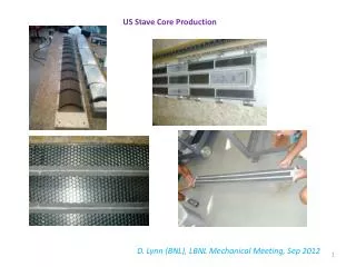
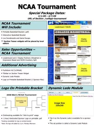
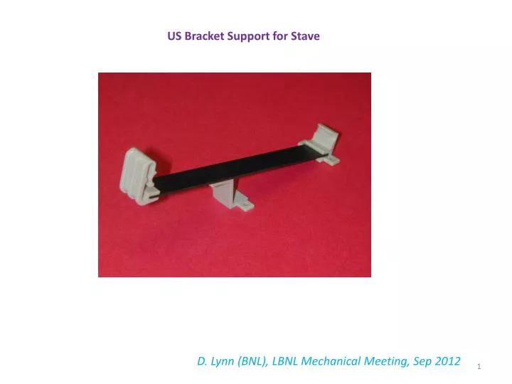
US Bracket Support for Stave. D. Lynn (BNL), LBNL Mechanical Meeting, Sep 2012. Bracket Design. Peek Flex-Edge. Peek Rigid-Edge. CF composite beam. Peek Z-Support. Main idea behind this approach is that the Rigid-Edge serves as the fiducial edge.

E N D
US Bracket Support for Stave D. Lynn (BNL), LBNL Mechanical Meeting, Sep 2012
Bracket Design Peek Flex-Edge Peek Rigid-Edge CF composite beam Peek Z-Support • Main idea behind this approach is that the Rigid-Edge serves as the fiducial edge. • The Flex-Edge pushes stave against fiducial Rigid-Edge. • End insertion is very simple.
Detector Envelope and Lorentz Angle • With above detector envelope can probably do about 13 degrees Lorentz angle. • May go lower depending upon final envelope, but 10 degrees is probably not possible
Prototype I Carbon Fiber/Peek Bracket Prototypes Recently Built Spring 2012 • CF/Peek design is radiation hard. Peek creep shown not to be an issue. • Insertion tests with 1.3 m stave are very smooth as hoped. • Have iterated design (Prototype II) of flex part of bracket to keep stave in brackets should large (accidental) normal force be applied to stave. • Prototype I brackets were sent to the UK for evaluation.
Prototype I and Prototype II Flex Performance After initial testing, modified design to prevent stave from popping out Prototype I I Prototype II Prevents stave from falling down II Prototype I (now in UK) Prototype II (just now being finished)
Deflection as a function of force tests • Peek Flexible brackets were machined at Yale; production brackets to be injection molded. • However, excellent uniformity among brackets 2-4, and surprisingly close to Anatoli’s design point. • The surprise is due to our not knowing beforehand the modulus of our peek . • D. Lynn talk, Oxford, Feb 2012, discusses dependence of peek young’s modulus with annealing history. Note here that brackets 2-4 were annealed at Yale, bracket 1 was not!
Yale OGP Measurements of Prototype I • Measurements were quickly done at Yale • “Constellation” plots revealed more variation than desired • Yale has improved its assembly tooling for prototype II • Yale will more carefully make OGP measurements of prototype ii as they will have more time Height variations larger than desired Circles provide collinearity measurement Need line and two extra points circled in red when we measure next set of brackets Need also to determine if there is a bow in CF piece A Bracket Constellation Plot D C B O E
Brackets should push resonant frequency higher (buthave only measured with frame mimicking brackets up to now) Impact Response with Stave in Frame • Measure frequency response to impulse. • Compare frequency response of simple end support (lowest stave frequency) and frame support, where frame support mimics US style brackets with elastic peek brackets. • First resonant frequency with end support is 18 Hz (14 Hz is simulation value). First resonant frequency jumps to 156 Hz with frame (5 brackets) support. End Support Frame Support 18 Hz 60 Hz 108 Hz 156 Hz
New baseplate for DC-DC stave assembly will also include bracket mounting holes for bracket mount testing
New baseplate for DC-DC stave assembly will also include bracket mounting holes for bracket mount testing
Locking Ideas Old Slide (LSWG June 2011) but still relevant • We have not pursued a locking mechanism design pending a decision on where the fixation point should be. Choices are at z = 0 or z-outer (depends upon stave length). Note large active area gap between +/- z staves due to detector dead space shown below. Likely a z-outer fixation can be developed that increases the gap by an amount that is small compared to the naturally existing one. • The LSWG can be of benefit by working toward settling this issue. • Z fixation serves two purposes • Define fixed point for thermal contractions (or CME??). • Protect stave during services installation. • Maybe have z = 0 fixation for point 1 and • a temporary fixation point at z-outer for • services installation? Approx 1.3 mm dead space on detector
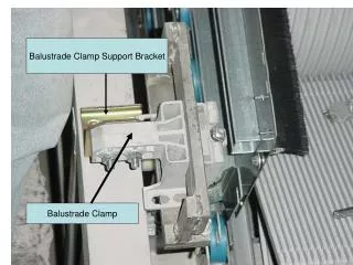
Locking Ideas • Separate bracket function from z-fixation/services relief function • Idea derived from UK drawing below Z-fixation pin and Services strain relief (don’t over-constrain in x and y) Hopefully can demonstrate pipes need not bend under EOS Drawing from R. Nickerson’s SLAC 2012 Talk
Radiation Length Prototype I Maybe be able to reduce by making width of brackets less (width in z direction). Radiation Length
Final Notes • Need to understand what region at z = 1.3 m looks like in terms on interconnect between barrels and services to decide how to lock in z and protect stave during services installation…are interlinks the default??? • With prototype II brackets and new baseplate we will measure profile of 1.3 m standard stave both warm and cold (have not done cold up till now) • What else needs to be addressed?