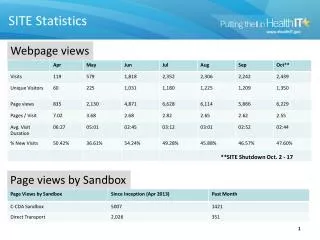
Download
1 / 12
130 likes | 386 Views
SITE TEST INTERFEROMETER ATMOSPHERIC DECORRELATION STATISTICS USE IN UPLINK ARRAY LINK BUDGETS. David Morabito and Larry D’Addario Jet Propulsion Laboratory California Institute of Technology for Presentation at the 13 th Ka-Band and Broadband Communications Conference

E N D
SITE TEST INTERFEROMETER ATMOSPHERIC DECORRELATION STATISTICS USE IN UPLINK ARRAY LINK BUDGETS David Morabito and Larry D’Addario Jet Propulsion Laboratory California Institute of Technology for Presentation at the 13th Ka-Band and Broadband Communications Conference September 2007Turin, Italy
Background • A two-element Site Test Interferometer (STI) has been deployed at the NASA Deep Space Network (DSN) tracking complex at Goldstone, California. • The two elements consist of 1.2-m diameter offset-fed reflector antennas. Acquisition of one year of atmospheric phase fluctuation data started in May 2007. • Data are being acquired in order to characterize the troposphere phase effects for the given STI baseline site • Baseline separation (256-m), • elevation angle (48.5) • frequency (20.2 GHz) of the ANIK-F2 geostationary satellite • The system was previously tested in Cleveland, Ohio at the system level, and is now deployed at Goldstone, California • Ref: Nessel, J. A., Acosta, R. J., and Morabito, D. D., “Goldstone Site Test Interferometer Phase Stability Analysis”, this proceedings.
Background (Contd.) • The objective is to measure and characterize the degree of tropospheric phase decorrelation for baselines with lengths up to 500 m at potential Next Generation Deep Space Network (NGDSN) candidate sites such as Goldstone, California • Because the troposphere is non-dispersive with respect to phase decorrelation, the results can be scaled to higher and lower frequencies like those envisioned to be utilized in the NGDSN communications links (7.2 and 32–40 GHz) given the present observations acquired at 20.2 GHz. • The results can also be scaled to other elevation angles • The calculation of the phase structure function exponent from the RMS phase time series allows conversion from the measured STI baseline to other distances. • The Goldstone site is being considered as one potential future site of a large array of small diameter antennas that are being planned to replace the aging monolithic structures of the current DSN. Similar experiments by other investigators have been conducted at other sites, and future experiments are being planned to characterize other potential DSN array sites.
Cumulative Statistics • The results of the first few months of phase stability measurements are discussed elsewhere [Nessel et al. 2007, these proceedings] • The acquired statistics are used to characterize the Goldstone site and compare with those extracted from similar experiments performed at other sites. • The purpose of this talk is to discuss for Ka-band phase decorrelation statistics from a STI can be conditioned to allow for estimation of atmospheric loss in uplink array spacecraft link budgets. • The use of an uplink array requires knowledge of atmospheric phase decorrelation effects. • Such techniques can be used by flight projects in telecommunications link budgets for a potential future array at a given site. • This experiment will allow the capability of the Goldstone site to support widely distributed antenna systems for future Ka-band communications links to be assessed, and later compared with similar measurements from other candidate sites. • For the application of the decorrelation experiment data into a telecommunications link budget, we identify the following general steps: • generation of statistics from STI measurements • conversion of STI statistics to a common reference for a particular array configuration • application of statistics for a particular link scenario using the given array configuration • presentation of a link budget example using acquired STI statistics
Generation of STI Phase Statistics • The fundamental observable is a time series of phase differences, (t), measured over a sufficiently long period between interferometer elements • The data have been filtered and conditioned, including trend removal of satellite motion and instrumental drift • From the differential phase (t) time series, statistics are generated every T seconds (T = 600 seconds). This time series is regarded as one output of the test interferometer of length rsti, frequency fsti, and elevation angle sti. • By design, the instrumental phase contributions should be negligible, so that the statistic represents effects of the atmosphere alone. • Residual instrumental effects are assumed to be independent of the atmosphere. • If these can be separately characterized, then it can be subtracted from the measured RMS, leaving the desired atmospheric contribution. • A statistically significant structure function can be derived from data sets much shorter than 1 year. • We plan to collect data for at least a year • It is instructive to partition statistics into seasonal and day/night subsets.
Conversion to Standard Reference • To facilitate comparison of results from different STI instruments and from different sites, we convert the raw results to those that would be obtained under standardized conditions. • RMS phase errors are converted to RMS delay errors • RMS delay errors are referenced to zenith by dividing by the air mass 1/sin(sti) at the test interferometer elevation angle sti, resulting in • The measured results can be scaled to baselines other than those of the test interferometer: • Kolmogorov theory predicts = 5/3 for rij << h, and rsti<< h, for baseline distances less than h = 1000-m (the thickness of the turbulent air layer). • Throughout the microwave spectrum (1-40 GHz), the atmosphere is non-dispersive, so the phase delay used here is the same as the group delay, and both are independent of frequency. Even for frequencies near the 22 GHz water line, there is insufficient water vapor in the atmosphere to cause any significant dispersion.
Application for Specific Link Scenario • The phase RMS time series has been converted to delay RMS and transformed from the test interferometer elevation angle to zenith. • We then derive the probability distribution of the RMS delay, and with a sufficiently long data set we can also obtain the cumulative distributions versus percentile () for selected categories. • The delay fluctuations on a telecom link budget involving a large array of ground antennas reduces the effective gain of the array as follows: • where G is the actual gain, G0 is the gain in the absence of the atmosphere, • N is the number of antennas in the array, each summation is over all antennas of the array, • f is the link frequency, is the link elevation angle, • rij is the baseline length between antenna i and antenna j. • (,rij) is obtained by scaling the measured fluctuations on the STI baseline to each baseline of the array, and from zenith to elevation angle (multiplying by 1/sin()). • A telecom engineer can then input this loss as an entry in a link budget table. • A conservative approach is to use the 90th percentile value of the fluctuation, such that the actual loss will be better than the estimate 90% of the time. • The dB equivalent loss is applied to the overall power (or power-to-noise) of the link.
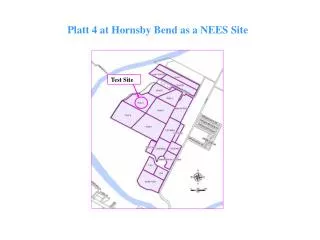
Link Example • A link scenario could involve a specific mission considering the use of a given array site for a particular mission phase • We consider the case of the use of a potential future uplink array to communicate over a high rate link to Mars. • Assume deep-space Ka-band frequency allocation (34.2-34.7 GHz) to a robotic Mars asset at 34.5 GHz (Earth to Mars). • A common approach, in an early phase of a proposed mission, is to perform a worst-case link analysis at some minimum elevation angle (e.g., 20) using conservative assumptions. • To calculate phasing loss due to atmospheric decorrelation, we consider a 19-element triangular close-packed array configuration of 12-m diameter antennas. • This particular configuration has the elements spaced such that shadowing is avoided down to an elevation angle of 10. North-South, Meters East-West, Meters Spatial configuration of nineteen12-m diameter antennas for the case of a triangular close-packed array.
Phasing Loss for Array Example 0.5 ps 1.0 ps 1.5 ps 7.2 GHz 2.0 ps 2.5 ps 3.0 ps Phasing Loss, dB 3.5 ps • Gain degradation (phasing loss) as a function of frequency for the case of the 19-element configuration, referenced to 20 elevation angle. • Each curve represents a different value of zenith RMS delay fluctuation relative to the STI baseline separation of 252-m. • Assumes that all baseline separations are < h = 1000-m, allowing for = 5/3. 4.0 ps 4.5 ps 5.0 ps 34 GHz Frequency, GHz
Conclusion • A STI has been deployed at Goldstone, California • STI phase statistics are being acquired in order to characterize the site • We have shown how these statistics can be conditioned and applied in link telecom budgets for potential future arrays at this site.
Acknowledgements • We acknowledge and appreciate the assistance and cooperation of the NASA Deep Space Network and the DSS-13 station crew. • We also want to thank Yuhsyen Shen for support of this work. • The research described in this publication was carried out at the Jet Propulsion Laboratory, California Institute of Technology, under a contract with the National Aeronautics and Space Administration.