Download
1 / 35
470 likes | 1.23k Views
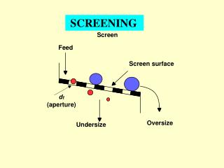
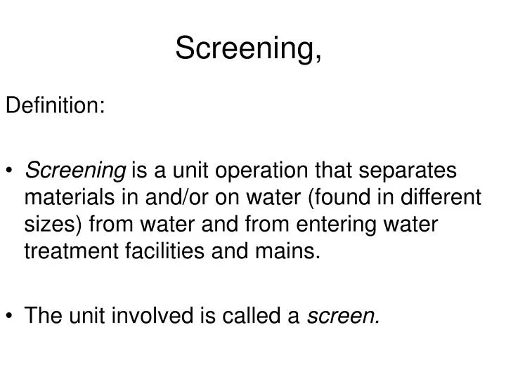
Screening, . Definition: Screening is a unit operation that separates materials in and/or on water (found in different sizes) from water and from entering water treatment facilities and mains. The unit involved is called a screen. .

E N D
Screening, Definition: • Screening is a unit operation that separates materials in and/or on water (found in different sizes) from water and from entering water treatment facilities and mains. • The unit involved is called a screen.
Where are Screens Located Within Treatment Plants or Systems
Legend Sluice Gate Bar Screen Motor Waste Sludge Pump Belt Filter Press
Classification of Screens • Opening size [Coarse, Medium and Fine] • Configuration [Bar Screens and Mesh Screens] • Method used to clean the entrapped materials (manually, mechanically, raked or water-jet cleaned) • Fixed or moving screen surface.
Classifications • Coarse Bar Racks – remove coarse debris (twigs, branches, rags, etc) - Spacing coarse 2 – 6 in medium 0.8 – 2in • Fine Screens • 3/8 to ½ in. (up to 10 mm or less, • book < 6 mm (1/4 in.))
Types of Screens • - hand clean coarse screens • - mechanically cleaned bar screens
Types of Screens • 1. Moving • 2. Fixed
Types of Screens There are many types of screens that can be used in water and wastewater treatment processes of which: 1 ‑ Bar or rack screens: Bar screens composed of parallel bars. Bars usually vertical or inclined 2 ‑ Band screens: Consists of a perforated belt passes over an upper and lower roller 3 ‑ Perforated plate screen: Consists of a fixed band of perforated screens 4 ‑ Wing screens: It has radial vanes which rotate on a horizontal axis 5 ‑ Disk screens: Circular perforated disk with or without supporting bars 6 ‑ Grating screens: Consists of two sets of parallel bars. 7 ‑ Mesh screens: Mesh screens composed of a fabric with mesh size depend on floating and suspending matter.
Bar Screens • Design Criteria of a Bar Screen : • Approach Velocity • Optimum Velocity : 0.6 m/s (through the screen opening) • Maximum Velocity : 0.75 - 1.0 m/s (to prevent entrapped materials being forced through the bars). • Minimum Velocity : 0.4 m/s to prevent deposition of solids. • Typical Range : 0.6 - 1.0 m/s • Headloss : • hL = 0.05 - 0.15 m for drinking water.hL = 0.10 - 0.40 m for sewage (wastewater) • Cleaning Mechanism: Manual Mechanical • Angle of Inclination (10-60 ) • Maximum head loss (cm)
Band or Belt Screens • Flexible woven wire mesh screens normally installed for a river supply. • Consists of sections of perforated mild steel plates connected together in a form of a band which is revolved by an electric motor. • Water passes inward through the screens and solid matter is washed off by high pressure water jets directed from inside of the screen.
Disk Screens and Drum Screens Similar in principle to band screens, differing only in the form of the moving screen. • Rotating metallic disc - partially immersed. • Solid caught in the screen are taken to the top, where they are scrapped by the moving screen. • Diameter : 2 to 5 m • Speed 0.05 m/s • Hollow drum. • One end of the drum is closed. • Water enters through the other end and passes out through the perforation. • Water jet is used for cleaning
Disposal of Screenings • Screenings is the waste materials collected from screens. Screenings should be properly disposed. Various methods of screening disposal were used such as: - burning, - burying, - digestion, - dumping into large bodies of water, - and shredding and returning it to wastewater collection or treatment system. • Inland burying is efficient in small treatment plants, while burning is best for medium and large treatment plants. Other methods cause problems and may need subsequent treatment. Digestion is used for large systems and in combination with the treatment of the organic portion of municipal solid waste.
Design of Coarse screens • - factors to consider • - clear openings between bars: opening needed - typically less than 2 ins., at 22 - 45 o incline • - location :installed ahead of grit chambers, may also be installed ahead of equalization tanks, if present. • - approach velocity: • at least 0.4 m/s to prevent deposition of solids, and should not exceed 0.9 m/s at peak flow rate • - head loss through screens - limited to 150 mm (6 in.) • - screens handling and disposal - quantity of screenings depends on the type of waste water, geographic location, screen size and weather • - screenings - vary from 3.5 - 80 m3/106 m3, about 80% moisture and density of 960 kg/m3 • - controls - operation cycle about 15 minutes for mechanically raked screens
Fixed Screens: Bar Screens • Bar racks (also called bar screens) are composed of larger bars spaced at 25 to 80 mm apart. The arrangement shown in the figure is normally used for shoreline intakes of water by a treatment plant. • The rack is used to exclude large objects; • the traveling screen following it is used to remove smaller objects such as leaves, twigs, small fish, and other materials that pass through the rack. • The arrangement then protects the pumping station that lifts this water to the treatment plant.
Bar Screens • Coarse screens or bar racks (< 2.5 inch openings) : • (1) removes large objects, rags, debris ; • (2) protects downstream pumps, valves, pipelines ; • (3) cleaning may be accomplished manually or mechanically ; • (4) mechanically cleaned bar racks (5/8 inch - 1-3/4 inch) typically used instead of coarse manually cleaned screens ; • (5) bar rack is inclined to facilitate , cleaning ; • (6) approach velocities should ensure self-cleaning, but not dislodge solids ; • (7) typical design : maximum velocity of 2.5 ft/sec through bar rack opening.
Microstrainer (Fine Filter) Microstrainer have been used to remove suspended solids from raw water containing high concentrations of algae. It consists of a fine fabric or screen wound around a metal drum
Head loss calculations determine the hydraulic head requirements for screen installation : C =0.7 for clean and 0.6 for clogged : empirical discharge coefficient to account for turbulence and eddy losses V : velocity of flow through openings in rack (m/s) v : approach velocity in upstream channel (m/s) g : acceleration due to gravity (m/s2)
Applying Bernuli before and after the screen • Or V12=V22 + 2g(h2 – h1)
Example A bar screen measuring 2 m by 5 m of surficial flow area is used to protect the pump in a shoreline intake of a water treatment plant. The plant is drawing raw water from the river at a rate of 8 m3/sec . The bar width is 20 mm and the bar spacing is 70 mm. If the screen is 30% clogged, calculate the head loss through the screen. Assume Cd = 0.60.
Solution: • For screens used in shoreline intakes, the velocity of approach is practically zero. Thus, • From the previous figure, the number of spacings is equal to one more than the number of bars. Let x number of bars,
Example • Design a bar screen chamber through which maximum, average, and minimum rates of flow are respectively 15, 7.5, and 3.0 cfs; the screen is such that there is one more space than there are bars; the outlet is controlled by a proportional weir such that depth of flow is directly proportional to rate of flow ?.
Solution • A schematic diagram of the proposed screen is given in previous slide. A number of assumption need to be made by the designer engineer concerning screen incline angel, a, flow velocity through screen, Vs, number of bars, Nb, bar's diameter, db, and space between bars, Sb. In this case we assume; α = 30o, Vs = 1.0 fps, Nb = 20 db = 0.25 inch, Sb = 1.0 in • Width of the screen, Ws, is equal to Ws = Number of Spaces x Space Distance = (20 +1) x 1 = 21 inch = 1.75 ft
Width of screen chamber, Wc, is equal to Wc = Width of screen + Bars thickness = 21 + (20 x 0.25) = 26 inch = 2.17 ft Length of the screen, Ls, is equal to Depth of the screen chamber, dc Ls = Sinus on angle α Flow through screen = Area available for flow x flow velocity Q = A x Vc A = Wc x dc Q = Qmax = 15 cfs Vc = 1.5 fps
Qmax dc = = 4.61 ft Wc x Vc Maximum depth of the screen chamber, dc, is maximum dc = dc + (0.67 to 1.00) = 5.28 ft Length of the screen Ls = dc/sin α = 9.22 ft Maximum flow velocity through the screen chamber, Vc, is Qmax Maximum Vc = = 1.62 fps Wc x maxdc = acceptable
ComminutorsShredding devices (communitor or grinder) : shreds material to 1/4 inch - 3/8 inch.
Comminutors are devices used in water and wastewater treatment either in combination with screens or independently with the aim of chopping the oversized suspended and/or floating material found in water and wastewater or escaping the screens before entering the treatment facilities and altering its operation. Comminutors consist of two sets of cutters one is fixed while the other is moving. The distance between the two sets equal to the size of chopped material required.
Comminution technology has been evolving quite rapidly in response to the increasing burden entrained solids have placed on treatment facilities. More advanced devices have been developed in rapid succession. The result has been an exciting and fluid race between the leading manufacturers to develop the best size reduction device. The latest grinder innovations to be introduced have coupled the power of twin shaft grinding with higher flow capabilities and screw screening systems. Here’s a rundown on the past and present state of the art in wastewater solids reduction
Comminutor Design For comminutor design, environmental engineer or designer need to supply manufacturer with the size of suspended and floating materials present in water to be treated and that after treatment along with its density and hydraulic and organic loadings. Accordingly manufacturer decides on the equipment needed to achieve the objective.