Download
1 / 90
900 likes | 1.1k Views
ECE 372 – Microcomputer Interfacing Laboratory. Pre-labs for ECE 372 Created by Ryan Mattfeld 12/17/12 Last Updated:12/17/12. ORIENTATION. Instructor Information and Syllabus. Instructor Name: Nilim Sarma Email: nsarma@clemson.edu Office Hours: Email to set up appointment.

E N D
ECE 372 – Microcomputer Interfacing Laboratory Pre-labs for ECE 372 Created by Ryan Mattfeld 12/17/12 Last Updated:12/17/12
Instructor Information and Syllabus • Instructor Name: NilimSarma • Email: nsarma@clemson.edu • Office Hours: Email to set up appointment. • Lab Manual can be found at http://www.clemson.edu/ces/departments/ece/resources/lab_manuals.html
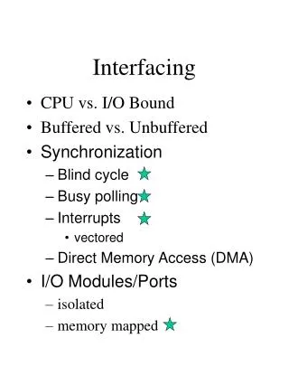
Introduction Objective: • Gain a better understanding of the functionality of a microcontroller. • Learn to interface devices with different modules on a microcontroller. Experiments: 10 experiments involving various modules and a final design project.
Final Design Project • Will combine at least two of the labs performed throughout the semester in a creative way • Worth 30% of final grade • Weekly Lab Reports for reference when making final design • Final lab report will be given on final design project
Equipments • The National Instruments ELVIS system . • Freescale MCU Project Board Student Learning Kit – Prototyping board with microcontroller interface. • Microcontroller - Freescale HCS12 Family, model MC9S12DT256. http://www.clemson.edu/ces/departments/ece/resources/lab_manuals.html
Software Development Environment. CodeWarrior IDE. • Text Editor for writing code. • Cross compiler to generate executables. • Loader program to load the executable on the microcontroller. • Debugger to perform runtime debugging.
Prerequisite • Familiarity with C programming language. • C tutorial available in lab manual.
Laboratory 1 Program • Program will count from 1-16 in binary using LEDs and in decimal using the LCD display. • Download the program from our section on Blackboard under the “information” section • Extract the program to your student (U:) drive • Open the “Lab 1” folder and open the .mpc file to edit the program • Take a few minutes to read the code and figure out what it should do
Laboratory 1 Program • Make sure to turn on both power switches on the NI-ELVIS board and connect the USB cables • Attempt to compile the code (ctrl+F7 is keyboard shortcut) • Identify and fix the error • Hit the “debug” button (green arrow with helicopter) • Run the code and see the result • Modify the code to count backwards
Final Reminders! • Store each lab as a separate file on your student server (copying an old lab folder and renaming it for new labs) • This ensures all necessary files are linked and provides your access to your previous lab code when you begin your final design project. • You can also access your student drive from any computer with internet access at: • https://netstorage.clemson.edu/ • Read over Lab 2 in the lab manual to be prepared for next week!
Device Memory Map $0000 - $03FF – Registers. $0000 - $0FFF – 4K Bytes EEPROM. $1000 - $3FFF – 12K Bytes RAM. External Memory $FF00 - $FFFF – Vectors. After reset the bottom 1k of the EEPROM ($0000 - $03FF) are hidden by the register space. Refer to MC9S12DT256 Device User Guide.
Laboratory 2 Preparation • Find the folder for Lab 1 that you used last week (stored on your student drive) • Copy the folder and rename it for Lab 2 • Open the .mpc file to edit and compile your code • In main.c, leave the header files and #pragma statement, but delete all code in void main(void) • We will define a command to read and write to the RAM of our microprocessor • ** We will begin writing at reading at memory location ***insert location here***
Laboratory 2 Code • We will create an easy method to access specific RAM memory addresses by using a #define statement • #define _P(ADDRESS) *(unsigned char volatile *)(ADDRESS) • This command will allow you to both read and write to a specific address in RAM. • Conceptually, in your program, you can use • _P(**desired memory address**) • Like you would use a variable to store and use information.
Laboratory 2 Code • Program goal: Write **** insert phrase here **** to RAM, then read from RAM to the LCD • At the beginning of your program, make sure you initialize the LCD using “LCDInit()” • Then, make sure that after every 8 characters you clear the LCD using “LCDClearDisplay()” • You can write to the LCD using the command “LCDPutChar()” • Use loops to write the phrase • Use conditional statement to clear display
Preparations for Next Week • Before next lab, read over Lab 3 in your lab manual, Application of a Digital Latch.
Lab 3 Preparation • Find the folder for Lab 2 that you used last week (stored on your student drive) • Copy the folder and rename it for Lab 3 • Open the .mpc file to edit and compile your code • This lab combines hardware with software • Uses 74LS374 Flip-Flop chip (D Flip-Flop)
74LS374 – D Flip Flop • Latch data from Input Pin to Output Pin when there is a rising edge on Clock Pin.
Laboratory 3 - Hardware Prep • The Input, 1D corresponds to the output, 1Q. Reference chip diagram: • Input: Switches (SW1 1 and SW1 2) • Output: LEDs (LED 1 and 2) • Intermediate Output (Port B LEDs) (Port B is hardwired to 4 LEDs) • Wire SW1 1 to 1D, SW1 2 to 2D • Wire 1Q to LED 1, 2Q to LED 2
Laboratory 3 – Microcontroller Comm. • Must wire inputs to microcontroller to manipulate input with code. • Wire SW 1 to PTT 0 (reference page 50 in lab manual for Port wiring table) • Wire SW 2 to PTT 1 • Clock Pulse Input: Pushbutton (PB1) to Port M 1 • Clock Pulse Output: Port M 0 to clock of Flip-Flop • Wiring complete!
Laboratory 3 – Software Prep • To use input and output registers on the microcontroller, must designate them for input or output in code. • DDR – Data Direction Register (0 for input, 1 for output) • Will use Port T, channels 0 and 1 for input, so we will set DDRT = 0x00; • Will use LEDs hard wired to Port B for output. • LEDs wired to Port B channels 4-7, set DDRB=0xF0; • Will use Port M channel 0 as input and Port M channel 1 as output, set DDRM = 0x01
Laboratory 3 – Main Function • Constantly loop, looking for switch input. Port T 0 and Port T 1 will change between 00, 01, 10, 11 based on switch configuration. • For each possible state of Port T, light corresponding LEDs (set Port B to appropriate values) (HINT: Port B 4-7 are wired to LOW active LEDs) • Finally, must generate clock pulse for D Flip-Flop • Check if Port M channel 1 is 0 (Push Buttons are low active). If it is, generate clock pulse on Port M channel 0. (Set PTM = 0x01 then reset it to 0x00)
Result • When complete, should have two displays: • 1) When you flip one of the switches, the LEDs hard wired to Port B should immediately change • 2) When you push Pushbutton 1, the switch values will travel through the Flip-Flop, and light the LEDs you wired your outputs to.
Preparations for Next Week • Before next lab, read over Lab 5 in your lab manual, Keypad Interfacing
Laboratory 5 Hardware Prep • Plug in Keypads with brass side of connector facing left • Keypad 1 Port T 1 • Keypad 2 Port T 2 • Keypad 3 Port T 5 • Keypad 4 Port T 3 • Keypad 5 Port T 6 • Keypad 6 Port T 7 • Keypad 7 Port T 4 • Keypad 8 Port T 0
Laboratory 5 software prep • Set Port T channels 0-3 as output and channels 4-7 as input using DDRT • New registers: PERx (Pull Enable Register) and PPSx(Polarity select Register) • PER and PPS work together to pull desired ports either high or low. • Pull Port T channels 4-7 high. • Enable Port T channels 4-7 for pulling(PERT = 0xF0) • Pull Port T channels 4-7 high (PPST = 0x00) (setting PPST to 0 pulls corresponding channel high)
Laboratory 5 Software Tools • Arrays can make keyboard interfacing easier: • unsigned char mask[16]={0xEE,0xDE,0xBE,0x7E, 0xED,0xDD,0xBD,0x7D, 0xEB,0xDB,0xBB,0x7B, 0xE7,0xD7,0xB7,0x77}; • unsigned char key[16]={'D','1','2','3', 'A','4','5','6', 'B','7','8','9', 'C','*','0','#'};
Laboratory 5 Code Flow Chart START INITIALIZE PORT T INITIALIZE (proper header files, declarations, and definition) No DETERMINE IF A SPECIFIED COLUMN IS ACTIVE IN THE ACTIVE ROW TURN ON 1 ROW AT A TIME Yes SEND THE PRESSED KEY TO THE LCD DISPLAY
Preparations for Next Week • Before next lab, read over Lab 4 in your lab manual, Interrupts
Laboratory 4 Wiring Diagram +5V Port P 0 Port P 1 Gnd
Laboratory 4 Software Prep • INPUTS • Port P 0 and 1 should be used as interrupts • Port P generates interrupt vector 56 (reference lab manual page 51 for vector interrupt table) • Registers: • DDRP = 0x00; (interrupts are inputs) • PERP = 0x03; (Enable pulling for interrupt channels) • PPSP = 0x03; (Pull low so high active button will trip interrupt) • PIEP (Port Interrupt Enable Register) = 0x03; (This enables Port P 0 and 1 as interrupts)
Laboratory 4 Software Prep • OUTPUTS • LEDs hard wired to Port B will be outputs • DDRB = 0xF0; (Channels 4-7 are wired to the LEDs so they should be outputs) • LCD will constantly count from 0-9 • LCDInit(); • LCDClearDisplay();
Laboratory 4 Software Prep • LOGIC • Constantly loop to count from 0-9 on the LCD display • Create interrupt function (using interrupt 56, the interrupt vector corresponding to Port P) • Check PIFP to see which interrupt was triggered • Light LEDs to reflect which interrupt was triggered • Reset Port P flags by setting the PIF(Port Interrupt Flag) register to a 1 for each channel you want to reset
Preparations for Next Week • Before next lab, read over Lab 7 in your lab manual, Rotary Pulse Generator
Laboratory 7 Wiring Diagram Rotary Pulse Generator Port P 0 Port J 7
Laboratory 7 Software Prep • INPUT • Port P 0 and Port J 7 are interrupts wired to Output A and Output B • Rotate Right Increase position • Rotate Left Decrease position • Change in voltage produces interrupt • Can determine which direction Rotary Pulse Generator turns based on interrupt and state of Port P 0, Port J 7
Laboratory 7 Software Prep • INPUT • Interrupt Vector for Port P • Interrupt Vector for Port J • Two interrupt functions • Set Port P 0 and Port J 7 as inputs • Set PERP and PERJ to enable Port P 0 and Port J 7 for pulling
Laboratory 7 Software Prep • OUTPUT • Port B LEDs will be used to show rotation in rotary pulse generator • Set Port B 4-7 as output • Initialize Port B LEDs off (Low Active)
Laboratory 7 Software Prep • LOGIC • Pulling registers high and low is essential • Interrupt trigger requires voltage change • As pulse generator rotates, voltage changes from low to high and high to low. • Pull high if next voltage change is high low • Pull low if next voltage change is low high