Download
1 / 16
190 likes | 434 Views
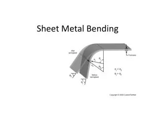
Finite element analysis of springback in L-bending of sheet metal. Y.E. Ling H.P. Lee B.T. Cheok. 7 February 2007. A Presentation by: Rose Wieland. Overview. Introduction Set up Effects of Die Clearance Effects of Step Size Conclusion/Recommendations. Introduction.

E N D
Finite element analysis of springback in L-bending of sheet metal Y.E. Ling H.P. Lee B.T. Cheok 7 February 2007 A Presentation by: Rose Wieland
Overview • Introduction • Set up • Effects of Die Clearance • Effects of Step Size • Conclusion/Recommendations
Introduction • Increasing demand for tight tolerances • Springback is biggest problem to tolerances • FEM models allow for effect of die clearance, die radii, and step size to be analyzed • Idea of how to minimize springback
History • 1958 – first mathematical model for springback corrections • 1991/1992 – FEM models used to analyze springback • Never in the paper is the accuracy of FEM models versus real experimental data discussed!
FEM Model • Die, punch, and pressure pad rigid • Workpiece is a deformable mesh • Die step height, step distance, die clearance, and die radii varied • Material used : AL2024-T3
Bend Leg analysis Bend leg curves between clearances of 1t and 0.8 t with maximum between 0.9 t and 0.95 t Otherwise, bend leg remains strait
Effects of Die Radius • K = springback factor • A = bend angle after springback • A1= bend angle during bending Springback factor of 1 most desirable
Design Recommendations • Die radius, clearance, and step height and distance all effect springback • Die radius and clearance have greatest effect • Effects are exclusive and additive i.e. die radius = 2.0t die clearance = 0.75t; step height = 0.2t step distance = 0t. springback reduction for die radius 2.0t and die clearance 0.75t is 1.37◦ springback reduction for using a step height of 0.2t and step distance 0t at that die radius and clearance is 1.08◦ The total springback reduction is 1.37◦ + 1.08◦ = 2.45◦ (values from Table 2 and Table 3)
Accounting for Elongation • Radius most important factor to elongation • Bend leg elongation only happens at clearance less than the thickness • Step height and step distance do not alter bend allowances significantly
Conclusion • Established trends for effect of die clearance, die radius, step height and distance • Need for research with other materials • This research took 1000+ hours • Perhaps small samples of other materials could be tested to show trends
References • [1] A.G. Gardiner, The spring back of metals, Trans. ASME, J. Appl.Mech. 79 (1957) 1–9. • [2] W. Johnson, T.X. Yu, Springback after the biaxial elastic-plastic pure bending of a rectangular plate – I, Int. J. Mech. Sci. 23 (10) (1981)619–630. • [3] W. Johnson, T.X. Yu, On the range of applicability of results forthe springback of an elastic/perfectly plastic rectangular plate aftersubjecting it to biaxial pure bending – II, Int. J. Mech. Sci. 23 (10)(1981) 631–637. • [4] R.A. Ayres, SHAPESET: a process to reduce sidewall curl springbackin high-strength steel rails, J. Appl. Metalworking 3 (2) (1984)127–172. • [5] C. Wang, G. Kinzel, T. Altan, Mathematical modeling of planestrainbending of sheet and plate, J. Mater. Proc. Tech. 39 (3/4)(1993) 279–304. • [6] Y.K.D.V. Prasad, S. Somasundaram, Mathematical model for bendallowance calculation in automated sheet-metal bending, J. Mater. • Proc. Tech. 39 (3/4) (1993) 337–356.[7] D.K. Leu, A simplified approach for evaluating bendability andspringback in plastic bending of anisotropic sheet metals, J. Mater.Proc. Tech. 66 (1997) 9–17. • [8] J.C. Nagtegaal, L.M. Taylor, Comparison of implicit and explicitfinite element methods for analysis of sheet forming problems FESimulationof 3-D Sheet Metal Forming Processes in AutomotiveIndustry, 894, VDI, Berichte, 1991, pp. 705–725. • [9] A.P. Karafillis, M.C. Boyce, Tooling design in sheet metal formingusing springback calculations, J. Mech. Sci. 34 (1992) 113–131. • [10] H.B. Sim, M.C. Boyce, Finite element analyses of real time stabilitycontrol in sheet metal forming processes, ASME J. Eng. Mater.Technol. 114 (1992) 80–188. • [11] M.J. Finn, P.C. Galbraith, L. Wu, J.O. Hallquist, L. Lum, T.L. Lin,Use of a Coupled Explicit–Implicit Solver for Calculating SpringBack in Automotive Body Panels, Livermore Software TechnologyCorporation, Livermore, CA, 1992. • [12] L. Wu, C. Du amd, L. Zhang, Iterative FEM Die surface designto compensate for springback in sheetmetal stampings, in:Proceedings of NUMIFORM ’95, Ithaca, NY, 1995, pp. 637–641.[13] A.P. Karafillis, M.C. Boyce, Tooling and binder design for sheetmetal forming processes compensating springback error, Int. J. Mach.Tools Manuf. 36 (4) (1996) 503–526. • [14] M. Sunseri, J. Cao, A.P. Karafillis, M.C. Boyce, Accommodation ofspringback error in channel forming using active binder force control:numerical simulations and experiments, ASME J. Eng. Mater.Technol. 118 (1996) 426–434. • [15] Y. Ming, K. Manabe, H. Nishimura, Development of an intelligenttool system for flexible L-bending process of metal sheets, SmartMater. Struct. 7 (4) (1998) 530–536. • [16] I.N. Chou, C. Hung, Finite element analysis and optimization onspringback reduction, Int. J. Mach. Tools Manuf. 39 (3) (1999)517–536. • [17] M. Samuel, Experimental and numerical prediction of springbackand side wall curl in U-bending of anisotropic sheet metals, J. Mater.Proc. Tech 105 (3) (2000) 382–393. • [18] N. Narkeeran, M. Lovell, Predicting springback in sheet metal forming:an explicit to implicit sequential solution procedure, Finite Elements,Anal. Des. 33 (1) (1999) 29–42. • [19] Baumeister, Avallone, Mark’s Standard Handbook For MechanicalEngineers, 8th ed., McGraw-Hill, 1979. • [20] G. Sachs, Principles and Methods of Sheet Metal Fabricating, 2nded., Reinhold Publishing Corporation, New York, 1966.