Download
1 / 17
170 likes | 397 Views
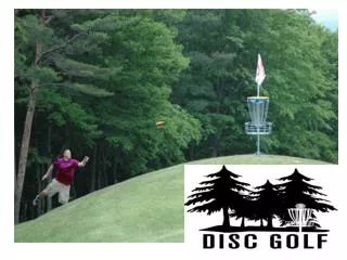
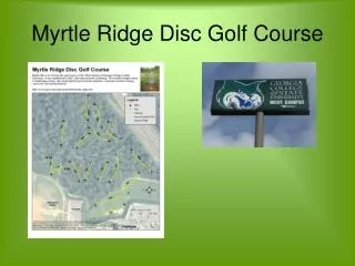
Disc Golf Disc Locator. Trevor Henry Project Advisor: John Spinelli. What is Disc Golf and Why this project?. What is Disc Golf? Outdoor sport played much like the game of golf Object is to throw the disc into the chain basket in as few throws as possible Why this Project? Save Money

E N D
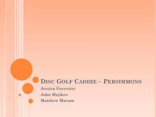
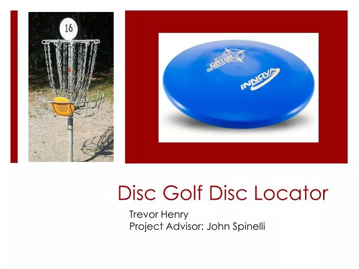
Disc Golf Disc Locator Trevor Henry Project Advisor: John Spinelli
What is Disc Golf and Why this project? • What is Disc Golf? • Outdoor sport played much like the game of golf • Object is to throw the disc into the chain basket in as few throws as possible • Why this Project? • Save Money • Save Time
Goals of the Project: • Handheld device • Battery powered • Visual information to tell distance and direction • Easy to use • Disc with a Chip • Transmits signal using battery power • Has negligible interference with flight • Transmitter + Disc < 200 grams (max weight rule)
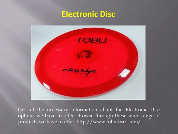
Disc Used: Innova Star Gator Mid-Range Disc Diameter = 21.2 cm Wing width = 1.3 cm Rim depth = 1.4 cm Weight = 172.2 grams
Design Process: Adding Weight Experiment 1 Quarter = 5.6 grams Conclusion: About 28 grams can be added to disc
Design Process: Choosing Wireless System • RFID (Radio Frequency Identification) • Passive or Active • Active Transmitter • Phased Array • Directional Antenna What I chose: • Active Transmitter & Directional Antenna
What I chose: Transmitter • RF Link Transmitter 434 MHz • Amplitude Shift Keying • Range 500 ft. (perfect conditions) • Supply Voltage: 3V – 12 V • Weight: < 1 Quarter • Height: < 1 inch • Width: < .5 inch
What I chose: Receiver • RF Link Receiver 434 MHz • Amplitude Shift Keying • Range 500 ft. (perfect conditions) • Supply Voltage: 5V • Height: < 2 cm • Width: < 2 inches
First Step: Communication of Transmitter and Receiver • Using the data sheets of the chips, the chips were set up and powered on a breadboard • Tried a non wave signal for input data on transmitter • This did not yield an output on the receiver • Used a 2V peak to peak square wave signal with 1V DCoffset • Yielded a readable output
Experiment 2: Communication Distance Used oscilloscopes and wave generators between rooms N106 & N100
Ongoing Tasks: Attaching Components to Disc 3V Button Cell to power transmitter Push button switch to make transmitter active Use a 555 timer or develop a square wave generator to input data Develop a casing such that components won’t be harmed when the disc is thrown
Ongoing Tasks: Handheld Device Attach a switch to turn on and off the device Develop a directional antenna Connect antenna to receiver Use a 5v battery source Attach a voltmeter to receiver output so that the user can determine distance to disc
What I learned: Read data sheets carefully How to set up voltage sources correctly Time is deceiving
Acknowledgements Advisor: Professor John Spinelli Lab Manager: Gene Davison