Download
1 / 32
320 likes | 326 Views
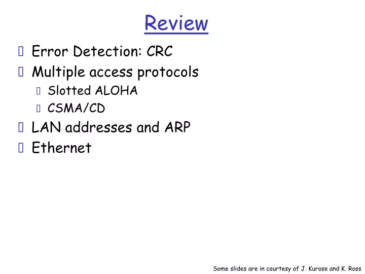
Review. Error Detection: CRC Multiple access protocols Slotted ALOHA CSMA/CD LAN addresses and ARP Ethernet. Some slides are in courtesy of J. Kurose and K. Ross. Overview. Ethernet Hubs, bridges, and switches Wireless links and LANs Last lecture on data link layer!.

E N D
Review • Error Detection: CRC • Multiple access protocols • Slotted ALOHA • CSMA/CD • LAN addresses and ARP • Ethernet Some slides are in courtesy of J. Kurose and K. Ross
Overview • Ethernet • Hubs, bridges, and switches • Wireless links and LANs • Last lecture on data link layer!
Ethernet Frame Structure Sending adapter encapsulates IP datagram (or other network layer protocol packet) in Ethernet frame Preamble: • 7 bytes with pattern 10101010 followed by one byte with pattern 10101011 • used to synchronize receiver, sender clock rates
Ethernet Frame Structure (more) • Addresses: 6 bytes • if adapter receives frame with matching destination address, or with broadcast address (eg ARP packet), it passes data in frame to net-layer protocol • otherwise, adapter discards frame • Type: indicates the higher layer protocol, mostly IP but others may be supported such as Novell IPX and AppleTalk) • CRC: checked at receiver, if error is detected, the frame is simply dropped
Unreliable, connectionless service • Connectionless: No handshaking between sending and receiving adapter. • Unreliable: receiving adapter doesn’t send acks or nacks to sending adapter • stream of datagrams passed to network layer can have gaps • gaps will be filled if app is using TCP • otherwise, app will see the gaps
No slots adapter doesn’t transmit if it senses that some other adapter is transmitting, that is, carrier sense transmitting adapter aborts when it senses that another adapter is transmitting, that is, collision detection Before attempting a retransmission, adapter waits a random time, that is, random access Ethernet uses CSMA/CD
1. Adaptor gets datagram from and creates frame 2. If adapter senses channel idle, it starts to transmit frame. If it senses channel busy, waits until channel idle and then transmits 3. If adapter transmits entire frame without detecting another transmission, the adapter is done with frame ! 4. If adapter detects another transmission while transmitting, aborts and sends jam signal 5. After aborting, adapter enters exponential backoff: after the mth collision, adapter chooses a K at random from {0,1,2,…,2m-1}. Adapter waits K*512 bit times and returns to Step 2 Ethernet CSMA/CD algorithm
Jam Signal: make sure all other transmitters are aware of collision; 48 bits; Bit time: 0.1 microsec for 10 Mbps Ethernet ;for K=1023, wait time is about 50 msec Exponential Backoff: Goal: adapt retransmission attempts to estimated current load heavy load: random wait will be longer first collision: choose K from {0,1}; delay is K x 512 bit transmission times after second collision: choose K from {0,1,2,3}… after ten collisions, choose K from {0,1,2,3,4,…,1023} Ethernet’s CSMA/CD (more)
CSMA/CD efficiency • Tprop = max prop between 2 nodes in LAN • ttrans = time to transmit max-size frame • Efficiency goes to 1 as tprop goes to 0 • Goes to 1 as ttrans goes to infinity • Much better than ALOHA, but still decentralized, simple, and cheap
Overview • Ethernet • Hubs, bridges, and switches • Wireless links and LANs
Interconnecting LAN segments • Hubs • Bridges • Switches • Remark: switches are essentially multi-port bridges. • What we say about bridges also holds for switches!
Interconnecting with hubs • Backbone hub interconnects LAN segments • Physical layer devices • Extends max distance between nodes • But individual segment collision domains become one large collision domian • if a node in CS and a node EE transmit at same time: collision • Can’t interconnect 10BaseT & 100BaseT
Bridges • Link layer device • stores and forwards Ethernet frames • examines frame header and selectively forwards frame based on MAC dest address • when frame is to be forwarded on segment, uses CSMA/CD to access segment • transparent • hosts are unaware of presence of bridges • plug-and-play, self-learning • bridges do not need to be configured
collision domain collision domain bridge = hub = host LAN segment LAN segment Bridges: traffic isolation • Bridge installation breaks LAN into LAN segments • bridges filter packets: • same-LAN-segment frames not usually forwarded onto other LAN segments • segments become separate collision domains LAN (IP network)
Forwarding • How do determine to which LAN segment to forward frame? • Looks like a routing problem...
Self learning • A bridge has a bridge table • entry in bridge table: • (Node LAN Address, Bridge Interface, Time Stamp) • stale entries in table dropped (TTL can be 60 min) • bridges learn which hosts can be reached through which interfaces • when frame received, bridge “learns” location of sender: incoming LAN segment • records sender/location pair in bridge table
Filtering/Forwarding When bridge receives a frame: index bridge table using MAC dest address if entry found for destinationthen{ if dest on segment from which frame arrivedthen drop the frame else forward the frame on interface indicated } else flood forward on all but the interface on which the frame arrived
Bridge example Suppose C sends frame to D and D replies back with frame to C. • Bridge receives frame from from C • notes in bridge table that C is on interface 1 • because D is not in table, bridge sends frame into interfaces 2 and 3 • frame received by D
Bridge Learning: example • D generates frame for C, sends • bridge receives frame • notes in bridge table that D is on interface 2 • bridge knows C is on interface 1, so selectively forwards frame to interface 1
Interconnection without backbone • Not recommended for two reasons: - single point of failure at Computer Science hub - all traffic between EE and SE must path over CS segment
Backbone configuration Recommended !
Some bridge features • Isolates collision domains resulting in higher total max throughput • limitless number of nodes and geographical coverage • Can connect different Ethernet types • Transparent (“plug-and-play”): no configuration necessary
Bridges vs. Routers • both store-and-forward devices • routers: network layer devices (examine network layer headers) • bridges are link layer devices • routers maintain routing tables, implement routing algorithms • bridges maintain bridge tables, implement filtering, learning and spanning tree algorithms
Routers vs. Bridges Bridges + and - + Bridge operation is simpler requiring less packet processing + Bridge tables are self learning - All traffic confined to spanning tree, even when alternative bandwidth is available - Bridges do not offer protection from broadcast storms
Routers vs. Bridges Routers + and - + arbitrary topologies can be supported, cycling is limited by TTL counters (and good routing protocols) + provide protection against broadcast storms - require IP address configuration (not plug and play) - require higher packet processing • bridges do well in small (few hundred hosts) while routers used in large networks (thousands of hosts)
Not an atypical LAN (IP network) Dedicated Shared
Overview • Ethernet • Hubs, bridges, and switches • Wireless links and LANs
802.11b 2.4-5 GHz unlicensed radio spectrum up to 11 Mbps widely deployed, using base stations 802.11a 5-6 GHz range up to 54 Mbps 802.11g 2.4-5 GHz range up to 54 Mbps All use CSMA/CA for multiple access All have base-station and ad-hoc network versions IEEE 802.11 Wireless LAN
Base station approch • Wireless host communicates with a base station • base station = access point (AP) • Basic Service Set (BSS) (a.k.a. “cell”) contains: • wireless hosts • access point (AP): base station • BSS’s combined to form distribution system (DS)
Ad Hoc Network approach • No AP (i.e., base station) • wireless hosts communicate with each other • to get packet from wireless host A to B may need to route through wireless hosts X,Y,Z • Applications: • “laptop” meeting in conference room, car • interconnection of “personal” devices • battlefield • IETF MANET (Mobile Ad hoc Networks) working group
IEEE 802.11: multiple access • Collision if 2 or more nodes transmit at same time • CSMA makes sense: • get all the bandwidth if you’re the only one transmitting • shouldn’t cause a collision if you sense another transmission • Collision detection doesn’t work: hidden terminal problem