Download
1 / 14
140 likes | 275 Views
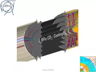
BPIX Cooling Status. W. Bertl, PSI. Time for design studies is now over ! We have entered the period of testing and verifying our design goals. 3 main objectives : Cooling plant ( construction , operation , safety requirements , control )

E N D
BPIX Cooling Status W. Bertl, PSI W. Bertl, PSI
Time for design studiesisnowover ! Wehaveenteredtheperiodoftestingandverifyingour design goals. 3 mainobjectives: Cooling plant (construction, operation, safetyrequirements, control) BPIX coolingloops (coolingperformance, variousdetectoroperatingconditions) Sensor cooling (heatconductionto CO2 coolant at full LHC operation) W. Bertl, PSI
Cooling Plant Prototype built, testedandoperatedbyCerngroups. (seeD’Auria’stalk) W. Bertl, PSI
Cooling Loops A fullscalereplicaof 50% ofthe final detectorpipinghasbeenbuiltbyUni ZH. Pipe extensiontothesupplytube not shown on thispicture representing –x and +x sideof half of BPIX W. Bertl, PSI
Cooling Loops One half ofthereplicaisnow at Cern. The second half currently at ETH ZH forcleaning. (will beshippedtoCernsoon) Testingofitscoolingperformanceundervarious thermal loadsassumingfulloronlypartsofthedetectorunder power over a temperaturerangebetween --30˚C and +20˚C. see Robert Becker’stalk W. Bertl, PSI
Sensor Cooling Goal: Sensor temperaturesufficientlylow such thatno thermal runawayandreasonablelowleakagecurrent (typ. < -2˚C) Assumption: CO2 inlet temperature: -20˚C Luminosity: int. fluence: 250 Sensor temperature depends on : pipe temperature expected: L1 = -15˚, L2 = -14.5˚, L3 = -15˚, L4 = -15.5˚ power dissipation per module: L1= 7W, L2= 3W, L3 = 2.4W, L4= 2.3W contact surface contact material see results of test measurement (next slide) Fortheworstcase at layer 1 about 70% of thermal loadisdissipatedbythe ROC, 30% bythesensor. W. Bertl, PSI
Sensor Cooling The ROC is in directcontactwiththe CFK baseplate (basestrips) whicharegluedtothecoolingpipes. The pipeposition on the CFK is such thatthe hottest partofthe ROC (peripherallogic) isclosesttothepipes. This design isverysimilartothepresentBpixexceptthatthefuturelayer 1 will beassembledusingbaseplatesinsteadofstripswhich will improvethe thermal conduction. Tests withdummymodulesimproving thermal conductionbyvariousmethodshavebeendoneusingwatercooling(seenextslide). Extrapolation toexpectedfutureconditionsand CO2 coolingseeovernextslide. W. Bertl, PSI
Sensor ΔT test Test setup similar as planned for layers 2-4, however standard CFK used with ~10 times worse heat conductivity than foreseen for final assembly (will be CFK K1100) Max. power in the test: 2 W/module Note: Layer 1 will have a 3 times larger contact surface than in the test W W. Bertl, PSI
Expected Sensor Temp. ...based on P=2W test result. CO2 temperature at -20˚C (-30˚C is possible) Note: At -2 deg. sensor current expected just below 50% of PS-limit. For 500 fb-1 @ -2 deg. expect that PS-limit of 20mA is hit. * This is a very conservative assumption W. Bertl, PSI
Verifying Sensor Cooling Proposedactionswithinnextmonths: Uni ZH will build a simple coolingloopwithsufficientspacetomountseveraldummymodules. Dummy modulesconsistingof CFK baseplate (strips), a ROC bumpbondedto a sensorandheatedwith thermal pads on top ofthesensor will bebuild at PSI. Mountingthosemodulestothetestloopusing different techniques (w/o conductingpaste, specialglues, ...) also done at PSI The assembledloopisplannedtobetestedwith 2-phase CO2 at nominal coolingtemperaturesusingthesmall CO2 cooling plant in Aachen. W. Bertl, PSI
Conclusion • Design of the cooling layout has been guided by calculations using the most advanced model specially developed for 2-phase CO2 microchannels (Thome et al). Results were confirmed by many measurements. (Cern, Aachen) • Extensive testing will be possible using the full scale replica resembling 50% of the final setup together with the full scale cooling plant prototype recently completed at Cern. Testing could start beginning 2014. • Building this replica has demonstrated that the full cooling system can be built and could stand the required pressure with large safety margins. • Sensor temperature expected to be sufficiently far below runaway temperature. This will be confirmed using a small test setup, however with full scale modules and pipes, in 2014. • The planned installation of new concentric stainless steel cooling pipes between the cooling plant and PP1 will allow temperatures down to -30 degree (at the BPIX entrance) which gives another safety margin for the sensor temperature. W. Bertl, PSI
Back-up slides W. Bertl, PSI
T & P along a loop ST-conv. ST-central slot Detector ST-return W. Bertl, PSI
Safety Issues Complete BPIX piping will be pressure tested to 160 bar. (Successfully done with cooling replica) Safety issues of the cooling plant see talk by Paola. Module temperature: On each z-side 6 cooling loops enter/leave the barrel section. We have enough lines available at the control cable (connector foreseen in central slot of supply tube) to equip each loop with 2 temperature sensors, mounted at the first/last module of the loop. An abnormal temperature reading could be used to shut down all (or selected) power supplies by DCS. W. Bertl, PSI