Download
1 / 11
110 likes | 247 Views
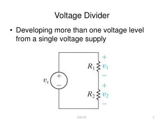
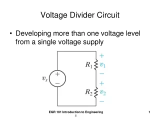
HV divider modifications. M. Raggi, T. Spadaro, P. Valente & G. Corradi, C. Paglia, D. Tagnani. Motivations. Ringing & shoulder of the signal… … and their effects on the time-over-threshold readout. Original divider. Equivalent resistance R eq = 3.36 M W

E N D
HV divider modifications M. Raggi, T. Spadaro, P. Valente & G. Corradi, C. Paglia, D. Tagnani
Motivations Ringing & shoulder of the signal… … and their effects on the time-over-threshold readout
Original divider Equivalent resistance Req= 3.36 MW At 1500 V maximum current is Imax=1500 V/ 3.36 MW = 446 mA Dissipated power: PR= V·I = 107 V × 446 mA = 48 mW on R=240 kWPR1= 2V·I = 214 V × 446 mA = 96 mW on R1=2RPtot=V·I = 446 mA × 1500 V = 670 mW total Req=3.36MW V0=1500
Divider with 1st dynode clamp First dynode clamp Quenching of d10 d11 d12 and anodeQuenching capacitorsHV decoupling resistor (10 KW) Req=2.9MW V0=1500 V Vclamp=280 V Req= 2.9 MW Tension on divider is (1500 – Vclamp)Imax=(1500V-Vclamp)/ 2.9 MW = 420 mA PR=VR × I = 100.8 V × 420 mA = 42.3 mW on each resistor (-6mW)Pdiodes= Vclamp × I = 280V × 420 mA = 117 mW ~ 60 mW per diode Ptot=Veq × I = 420 mA × 1500 V = 630 mWtotal
Gain model • We use • R=240 KW, V=voltage from HV supply • For the totally resistive (original) divider Req=14 R • G=P1NKiVia=KNVNa • Vi=V/(14R) • For the divider with diode clamp Req=12 R • G=K1(V-V0)aP2NKiVia=K1(V-V0)aKN-1V(N-1)a • Vi=(V-V0)/(12R)
Data/MC comparison Ratio between gain with resistive divider (old) and first dinode clamp divider (new) K1 is already saturated, and thus cannot increase the gain. Increasing the tension on first dynode is useless. Gain ratio can be improved by lowering the clamp voltage (but only 10% better at 120 V)
Final divider • 200 dividers already mounted • only 1 with discharges (due to bad cable)