Download
1 / 1
10 likes | 117 Views
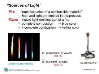
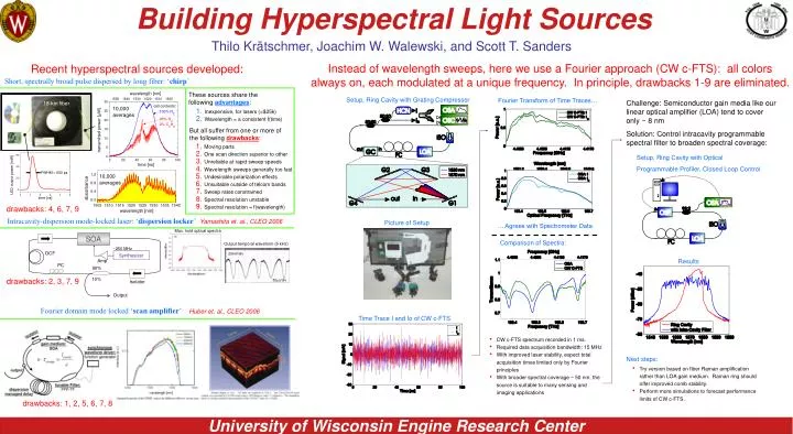
Building Hyperspectral Light Sources. 20mV/div. SOA. 50 m s/div. ~250 MHz. DCF. Synthesizer. Amp. PC. 90%. 10%. Isolator. Output. Thilo Krätschmer, Joachim W. Walewski, and Scott T. Sanders.

E N D
Building Hyperspectral Light Sources 20mV/div SOA 50ms/div ~250 MHz DCF Synthesizer Amp PC 90% 10% Isolator Output Thilo Krätschmer, Joachim W. Walewski, and Scott T. Sanders Instead of wavelength sweeps, here we use a Fourier approach (CW c-FTS): all colors always on, each modulated at a unique frequency. In principle, drawbacks 1-9 are eliminated. Recent hyperspectral sources developed: Short, spectrally broad pulse dispersed by long fiber: ‘chirp’ These sources share the following advantages: Setup, Ring Cavity with Grating Compressor Fourier Transform of Time Traces… Challenge: Semiconductor gain media like our linear optical amplifier (LOA) tend to cover only ~ 8 nm Solution: Control intracavity programmable spectral filter to broaden spectral coverage: 18-km fiber 10,000 averages Inexpensive, for lasers (<$25k) Wavelength = a consistent f(time) But all suffer from one or more of the following drawbacks: Moving parts One scan direction superior to other Unreliable at rapid sweep speeds Wavelength sweeps generally too fast Undesirable polarization effects Unsuitable outside of telcom bands Sweep rates constrained Spectral resolution unstable Spectral resolution = f(wavelength) Setup, Ring Cavity with Optical Programmable Profiler, Closed Loop Control 10,000 averages drawbacks: 4, 6, 7, 9 Intracavity-dispersion mode-locked laser: ‘dispersion locker’ Yamashita et. al., CLEO 2006 Picture of Setup … Agrees with Spectrometer Data Max. hold optical spectra Comparison of Spectra: Output temporal waveform (5 kHz) Results drawbacks: 2, 3, 7, 9 Fourier domain mode locked ‘scan amplifier’ Huber et. al., CLEO 2006 Time Trace I and Io of CW c-FTS • CW c-FTS spectrum recorded in 1 ms. • Required data acquisition bandwidth: 15 MHz • With improved laser stability, expect total acquisition times limited only by Fourier principles • With broader spectral coverage ~ 50 nm, the source is suitable to many sensing and imaging applications Next steps: • Try version based on fiber Raman amplification rather than LOA gain medium. Raman ring should offer improved comb stability. • Perform more simulations to forecast performance limits of CW c-FTS. drawbacks: 1, 2, 5, 6, 7, 8