Download
1 / 15
251 likes | 645 Views
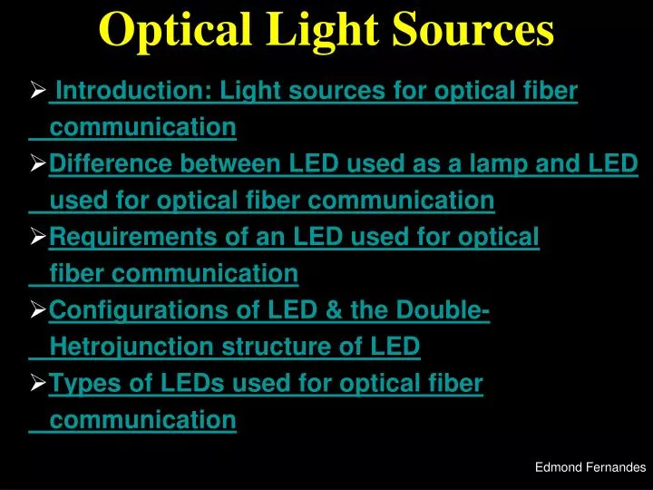
Optical Light Sources. Introduction: Light sources for optical fiber communication Difference between LED used as a lamp and LED used for optical fiber communication Requirements of an LED used for optical fiber communication Configurations of LED & the Double-

E N D
Optical Light Sources Introduction: Light sources for optical fiber communication Difference between LED used as a lamp and LED used for optical fiber communication Requirements of an LED used for optical fiber communication Configurations of LED & the Double- Hetrojunction structure of LED Types of LEDs used for optical fiber communication Edmond Fernandes
Types of LEDs used in optical fiber communication • Surface Emitter LEDs • Edge Emitter LEDs Edmond Fernandes
Surface Emitter LED (SLED) • Also known as Burrus or front emitters • Plane of the active light-emitting region is oriented perpendicular to the axis of the fiber Edmond Fernandes
Construction • A well is etched through the substrate of the device • The fiber is then cemented into the well. • Circular active area is 50μm in diameter and 2.5μm thick. Edmond Fernandes
Emission Pattern • Emission pattern is isotropic with a 120o half-power beam width. • This isotropic pattern from the SLED is called a Lambertian pattern • Power distribution is described by PD = P Cos θ • Where θ is the angle between the direction of the observation and the line orthogonal to the radiating surface • This implies that the source is equally bright when viewed from any direction but the power diminishes as Cos θ. • Thus the power is down to 50% of its peak when θ = 60o so that half power beam width is 120o Edmond Fernandes
Working • When the SLED is forward-biased, photons are generated in the p-GaAs layer. • The emission from the top surface is ensured by the upper n+ AlGaAS and lower p+ AlGaAs layers of the hetero-structure. • Therefore, radiance of the device in the forward direction is very high. Edmond Fernandes
Working • Although the fiber is properly aligned to optimize the coupling of the emitted radiation with the fiber, there is some loss due to the Lambertian distribution of radiation intensity. • The hetero-structure provides a means for confining charge carriers and optical power in the active region so that radiative recombination takes place. • Difference between refractive index of adjacent layers confines the optical power in the central GaAs. • SLED is more suitable for use with multimode fibers. Edmond Fernandes
Edge Emitting LED (ELED) Edmond Fernandes
(Active region) Construction • Edge emitters consist of an active junction region, which is the source of the incoherent light • This active region lies between two guiding layers Edmond Fernandes
(Guiding layers) Construction • The guiding layers both have a refractive index, which is lower than that of the active region but higher than the index of the surrounding material. • This structure forms a waveguide Edmond Fernandes
The waveguide Edmond Fernandes
Construction • To match the typical fiber core diameters (50 to 100μm), contact stripes for the edge emitters are 50 to 70μm wide. • Lengths of the active region are 100 to 150μm. (Contact stripes) Edmond Fernandes
Construction • The stripe geometry made by selective metallization of the top surface through a window opened in a SiO2 layer allows high current injection densities for the same drive current. • In other words, the power conversion efficiency is improved. (Stripe Geometry) Edmond Fernandes
Emission Pattern • ELED radiates a Lambertian pattern in the plane parallel to the edge and produces a beam that is much narrower in the plane perpendicular to the edge. • This emission pattern is more directional than that of the SLED • In the plane parallel to the junction where there is no waveguide effect, the emitted beam is lambertian (varying as Cos θ) with half power beam width of θІІ = 1200. • In the plane perpendicular to the junction half power beam width is of θ┴ ~ 250 to 350 Edmond Fernandes
Advantages • Enhanced waveguiding of the edge emitter enables to couple more power to a low (NA) fiber than a comparable surface emitter. • The stripe geometry allows higher carrier injection densities for a given drive current. • Substantially, this gives better modulation bandwidth of the order of several MHz. • ELED can be used with a single mode fiber Edmond Fernandes