Download
1 / 19
210 likes | 369 Views
A 90nm 512Mb 166MHz Multilevel Cell Flash Memory with 1.5MByte/s Programming. Adopted from ISSCC Dig. Tech. Papers, Feb.2005, Intel Corporation[2.6]. Presented By: Nadereh Hatami Class Presentation Advanced VLSI Design Course. Outline. Floating Gates introduction

E N D
A 90nm 512Mb 166MHz Multilevel Cell Flash Memory with 1.5MByte/s Programming Adopted fromISSCC Dig. Tech. Papers, Feb.2005, Intel Corporation[2.6] Presented By: Nadereh Hatami Class Presentation Advanced VLSI Design Course
Outline • Floating Gates introduction • Multilevel Flash Cell Approach • Device Information • Multilevel Cell Sense Budget • Stepped Gate (SG) Sensing • Negative Deselected Row (NDR) • Customer Selectable Output Drive • Technology • Conclusions
A Typical Flash Memory Cell Adopted From [2]
Device Information • 512Mb (8 partitions, 64Mb each) • 256 independently erasable blocks • Object/Control Mode Programming • 65ns Asynchronous mode access • Synchronous Burst • 166MHz zero wait state • 8W / 16W / Continuous Burst Modes • Selectable Output Strength • Low Power Operation • Deep Power-Down Mode (5uA) • 1.7 – 2.0V core power supply (VCC) • 1.35V – 2.0V output driver power supply (VCCQ)
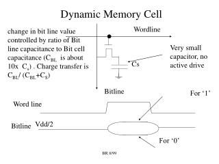
Max VT limited by Cell and Program Placement Performance L3 Program Verify Level 3 (PV3) Read Reference Level 3 (R3) Some sense budget components Floating Gate (FG) to FG Coupling Apparent VT Change due to ΔVS VT Margin Required for Sensing Program State Width Post Retention Bake Erase State Width Post Retention Bake L2 PV2 Increasing VT (~3V between R1 and R3) R2 L1 PV1 R1 Erase Verify (EV) L0 Min VT limited by Column Leakage Impact on Erase Count Multilevel Cell Sense Budget From [1]
Floating Gate (FG) to FG Coupling FG Coupling Drain Shields Poly 1 FG-FG Coupling
Cell A = L1 Cell B = L0 Cell A = L1 Cell B = L3 Apparent VT Change due to ΔVS • 128 Cells Read in Parallel • 1st Program Operation Places Cell A = L1 • 2nd Program Operation Places Cell B = L3 • Source Voltage Lowers for Cell A during L1 sense • Result: Lower Apparent VT From [1]
Minimizing FG-FG Coupling & ΔVS Programming cells in an 8Kbit region in a single program operation: • Eliminates impact of Apparent ΔVT due to ΔVS • Minimizes impact of FG-FG Coupling
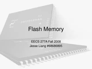
CG Sensing Voltage • SG Sensing uses a fixed reference current • CG Sensing uses a fixed gate voltage IDS 1 R Ref cell current varies depending on VT for CG sensing 2 R 3 R VGS Ref cell current is constant for SG sensing 1 2 3 Gate voltage varies for SG sensing Stepped Gate (SG) vs. Constant Gate (CG) Sensing From [1]
Stepped Gate Sensing Scheme Concept From [1]
Stepped Gate Sensing From [1]
Erase VT Distribution Comp Under-erased Cells Over-eased Cells Cell w/ -VT Swamps Comparator w/ NDR - VT w/o NDR Negative Deselected Row (NDR) IREF VEV 0V 0V From [1]
L3 PV3 Some sense margin components Sense Margin Improvement Floating Gate (FG) to FG Coupling VT Margin Required for Sensing Program State Width Post Retention Bake Erase State Width Post Retention Bake R3 L2 PV2 R2 • Result of Sense Margin Improvements • Can allow wider VT distribution to achieve faster program performance. • Can widen budget by lowering EV because Min VT is not limited by Column Leakage Impact on Erase. L1 PV1 R1 EV L0 Count Multilevel Cell Sense Margin Improvement Increasing VT (~3V between R1 and R3) From [1]
Customer Selectable Output Drive Customer Selectable Output Drive Strength for matching system load From [1]
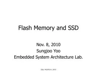
Prog ControlCircuits One Block ½ Partition ½ Partition Y-Select X-Decoder Sensing / Bitline Sel Die Size = 42.5mm2 Die Photo From [1]
Technology • Triple Well 90nm CMOS • 3 Cu Interconnect Layers • Dual Poly Layers, Co-Salicide • Flash Cell • Effective Bit Size 0.038μm2 • Tunnel Oxide Thickness 88Å • Interpoly Dielectric Thickness 140Å • Periphery Transistor Oxide Thickness • 150Å High Voltage • 45Å Low Voltage
Conclusions • Significant Sense Budget Consumers • FG-FG Coupling • Apparent VT change due to change in data pattern storage • Apparent VT change due to temperature change between cell placement verify and read. • Design Techniques that Improve Budget • 2-row programming • SG sensing • NDR • Combining 90nm CMOS technology with multilevel cell Flash and the design techniques that have been presented delivers world-class performance of: • 166MHz Synchronous Burst Read • 1.5 MByte/s Program
References [1] Intel, Folsom, CA, “A 90nm 512Mb 166Mhz Multilevel Cell Flash Memory With 1.5MB/s Programming”, ISSCC Dig. Tech. Papers, Feb. 2005 [2] Bauer, M. et al., “A Multilevel-cell 32Mb Flash Memory,” ISSCC Dig. Tech. Papers, pp.132-133, Feb., 1995. [3] Jan M. Rabaey, Anantha Chandrakasan, Borivoje Nikolic,” Digital Integrated Circuits, A Design Perspective,2th edition”, Book Slides. [4] ISSCC Press Kit 2005 [5] http://www.siliconfareast.com/flash-memory.htm [6] http://www.intel.com