Download
1 / 23
330 likes | 707 Views
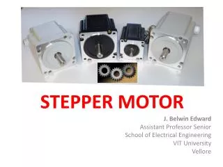
Interfacing Stepper motor to 8051 microcontroller A stepper motor is a special type of electric motor that moves in increments, or steps, rather than turning smoothly as a conventional motor does.

E N D
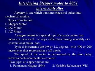
Interfacing Stepper motor to 8051 microcontroller A stepper motor is a special type of electric motor that moves in increments, or steps, rather than turning smoothly as a conventional motor does. Typical increments are 0.9 or 1.8 degrees, with 400 or 200 increments thus representing a full circle. The speed of the motor is determined by the time delay between each incremental movement. Stepper motor uses Permanent Magnet (PM) and Variable Reluctance (VR)
Motor Moves Each Time a Pulse is Received • Can Control Movement (Direction and Amount) Easily • Can Force Motor to Hold Position Against an Opposing Force
Construction • Permanent Magnet Rotor • Also Called the Shaft • Stator • Surrounds the Shaft • Usually Four Stator Windings Paired with Center-Tapped Common • Known as Four-Phase or Unipolar Stepper Motor
Stepper motors can be used in various areas of your microcontroller projects such as making robots, robotic arm, automatic door lock systemTypes of Stepper motor:1 . Unipolar stepper motor – 6 wires= 4 coils and 2 common2 . Bipolar stepper motor – 4 wires= 4 coils and no common terminals.
Half Stepping Full Stepping Working of Stepper Motor When only 1 coil is energized When 2 coil is energized
Stepper motors can be driven in two different patterns or sequences. namely, 1. Full Step Sequence2. Half Step Sequencewe will go through these sequences one by one.
Steps/Revolution = 360° Step Angle In 1 full step sequence, motor rotates by 1 tooth pitch. So, Number of Rotor teeth = Steps/ Revolution 4
Construction (con’t) • Center Tapped Common
Moving the Rotor Unstable Stable Rotor will ALWAYS seek a stable position.
Single-Coil Excitation - Each successive coil is energised in turn.
Two-Coil Excitation - Each successive pair of adjacent coils is energised in turn.
Interleaving the two sequences will cause the motor to half-step 8 step sequence = normal 4 step + wave drive 4 step.
Single-Coil Excitation Two-Coil Excitation Interleaved Single- and Two-Coil Excitation Half-Stepping
How Far Does It Move? • Step Angle • Arc Through Which Motor Turns With ONE Step Change of the Windings • Varies With Model of Stepper Motor (Depending on the number of teeth on stator and rotor) • Normally in Degrees • Step angle = 360/No. of Steps per Revolution • Commonly available no. of steps per revolution are 500, 200, 180, 144, 72, 48, 24
How Fast? Revolutions per Minute (RPM) The top electromagnet (1) is turned on, attracting the nearest teeth of a gear-shaped iron rotor. With the teeth aligned to electromagnet 1, they will be slightly offset from electromagnet 2. The top electromagnet (1) is turned off, and the right electromagnet (2) is energized, pulling the nearest teeth slightly to the right. This results in a rotation of 3.6° (1.8’) in this example. The left electromagnet (4) is enabled, rotating again by 3.6° (1.8’). When the top electromagnet (1) is again enabled, the teeth in the sprocket will have rotated by one tooth position; since there are 25(50) teeth, it will take 100(200) steps to make a full rotation in this example. The bottom Electromagnet (3) is energized; another 3.6° (1.8’) rotation occurs.
Drivers • May Need a Driver Circuit • Same Problem as Relays – May Draw Too Much Current • Types • Transistor Drivers • Usually a Darlington Pair • Darlington Arrays • Can Build It Yourself
Applications: • Used in • In instrumentation such as watches, clocks, etc. • Computer peripherals such as card readers, teleprinters, teletypes, dot matrix printers, etc. • Robotics