Download
1 / 36
360 likes | 478 Views
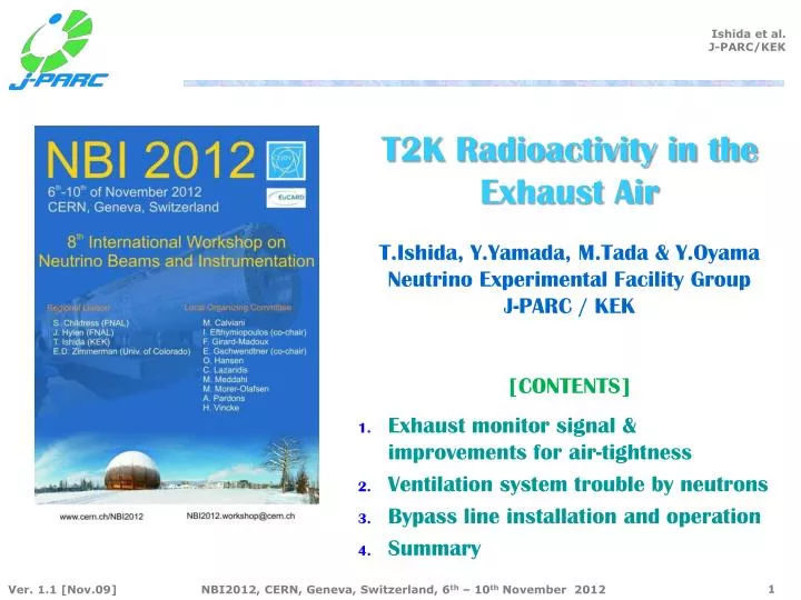
T2K Radioactivity in the Exhaust Air T.Ishida , Y.Yamada , M.Tada & Y.Oyama Neutrino Experimental Facility Group J-PARC / KEK [CONTENTS]. Exhaust monitor signal & improvements for air-tightness Ventilation system trouble by neutrons Bypass line installation and operation Summary .

E N D
T2K Radioactivity in theExhaust AirT.Ishida, Y.Yamada, M.Tada & Y.OyamaNeutrino Experimental Facility GroupJ-PARC / KEK[CONTENTS] • Exhaust monitor signal & improvements for air-tightness • Ventilation system trouble by neutrons • Bypass line installation and operation • Summary
Radiation Monitors • Exhaust air monitor (gamma): 3 pairs(S/BG) • NaI (TI) scintillation counter • Level of exhaust at upstream of the exhaust chimney stack. • Should be no signal during beam • < 0.5 mBq/cc for 3 month average • Environment air monitor (gamma): 3 • NaI (TI) Scintillation counter • level of environment at pits/machine rooms at TS / NU3 • Entry prohibited with signal > 10mBq/cc • NU2 exhaust is also monitored. • Area monitor (gamma/n): 4 pairs • Ionization chamber / 3He counter • Near the boarders of rad. controlled area • Gamma: < 0.3uSv/h [alert 0.8uSv/h] • Neutron: < 0.01uSv/h [alert 0.5uSv/h] • Integration over every 1 hour is used for PPS: limit: 0.5uSv/h x 1hr. NU2 TS BLUE311G NU3
Radiation monitors at TS Exhaust monitor 2 cells (A/B) for signal / B.G. NU3also has the monitors Area monitor Exhaust chimney stack BLU302 BLU312 YEL302 10L(3atm), 50mm thick Pb 3inφx3inNaI Environment monitor YEL301 • 10atm1inchφ×10inchHe-3 Prop. Counter • 41L(1atm) • 30mm thick Pb • 2inchφx2inchNaI
Exhaust monitor signal (Dec.24, 2009) TS exhaust NU3exhaust • MR R#28: The first continuous (20kW) beam • NU3 exhaust signal: Alert level= 0.05Bq/cc(Raw data) ⇔ Observed 0.06 Bq/cc • Beam operation was limited within only ~30min due to the radiation in the exhaust air. 0.05Bq/cc 0.07 0.05Bq/cc 07:50 01:50 20min 30min 20min 30min 25min 25min
Flow chart of NU3 Air Conditioning(Beam Operation Mode) Exhaust chimney stack Env. monitor OUR GUESS • If air tightness of the pits / rooms are bad, irradiated air in BD can go to the hot machine room • We started to investigate air flow / air tightness of pits / rooms Stair room mupit Hot machine room(1F) -20Pa polution test room (1F) Exhaust monitor Super-hot machine room (B1F) BeamDump Leak-tightened damper
[Hot Machine Room] 1st FL B1+ 4.5 stand [Super Hot] B1 FL 18.5 m Beam B2 FL Cross section of NU3 NU3: Neutrino Utility Building #3Beam Dump Pit /μPit 10.2m 1m 4m • Water circulation system for downstream half of DV and BD [B1] • Air circulation system for BD / MuPit[B1+4.5] Beam Dump Pit Muon Pit Beam Decay Volume 6m Passage Pipe/Duct Shaft Neutrino Utility Building #3 (NU3)
Drain water pit at muon pit 2010/1/6 • The drain port connecting to dump pit was closed by a flange with thinner pipe. Dump pit mpit 1/18 End of pipe under water level
Smoke Test • Test with a smoke machine, normally used for theater plays ! @ pipe/duct shaft (B2) 1/14 B1 Dump pit PS/DS • B2 PS/DS ⇒ smoke around heat-retention of square-ducts • / penetration of cable bundles • B1 ⇒ around service hatch / penetration of cable bundles
Air tightening (NU3) • Remove insulation around ducts seal with thin iron platesand caulking • Liquid silicone glue for the cable penetrations • Seal edges of concrete blocks at the delivery entrance to downstairs • Doors sealed with tape, repeat smoke tests to find remaining leaks
Jan. 23-24(MRRun#29) • NU3 exhaust monitor signal becomes much smaller • TSexhaust becomes 0.05Bq/cc with 2 hours of beam operation TS Exhaust 0.05Bq/cc 0.05Bq/cc NU3 exhaust
Flow of the Irradiated Air at NU3(beam commissioning mode) • Environment air monitor suggests that irradiated air was leaked into super-hot machine room from (air-tightened) dump pit cooling loop. • The air is going into 1F through service hatch and cable penetrations Clean air Negative Pressure control [-20Pa] Cable penetrations Service hatch Machine room (1F) Exhaust monitor 50mBq/cc (Raw data) Super-hot Machine Room (B1F) Dump pit Cooling loop 400mBq/cc Mupit cooling loop 30mBq/cc 900mBq/cc
Flow of the Irradiated Air at TS • Service pit / storage area covered with concrete blocks. Clean air chimney stack • Duct /pipe/ cable penetrations, including horn power cables. negative pressure Exhaust line (closed) Cooling loop Super hot Machine room Service Pit 300mBqcc 900mBq/cc The job was much much harder
Ex.Monitor Measurements • Both A(cell with 3 atm. exhaust air) and B(closed, BG cell) have signal • Gamma ray from 1F environment (outside of the cell) air is observed as common signal. • Radiation level in Exhaust = [ {A – Pedestal} - {B – Pedestal} ] / 3 (atm.) • 1mBq/cc~1.5mBq/cc law limit < 0.5mBq/cc [3-month average] • January: 3 days operation / 30days 0.5m x 10 = 5mBq/cc acceptable. (R#29, Jan.2010) 0.06Bq/cc Exhaust to enter into TS 3 mBq/cc Exhaust to enter into TS BLU302A(Signal) 0.045Bq/cc 0.5mBq/cc 0 BLU302B(BG)
TS air tightening(Feb.15-22) Need to do after every summer maintenance ! • Stop air flow coming out between concrete blocks by backup material and caulking We now learn how to sense tiny air leak by hand ! Smoke tester
Cable penetration Two Signal Cable trays Horn Power Cables Not only by smoke, but also by smell of smoke, we can find leak… apply neg.pressure to 1F: -100Pa Two square opernings
R#29 Jan.30~Feb.6 R#30 Feb.22~Mar.1 • 1.0 0.5mBq/cc (20kW, factor 2 reduction) • 0.5~0.8mBq/cc (27kW) 0.5mBq/cc
Add MVDs in the Underg. Vent Line (Mar.30~Apr.2,2010) • We doubted leak in the ducts to vent undergr. rooms MVD room press. control Inlet Filter Unit Inlet Filter Unit Ventilation FAN(inlet) Chimney stack To exhaust monitor Outlet HEPA Filter Unit New Motorized Volume Dumpers Ventilation FANS (outlet)
Install MVDMar.30~Apr.2 • Add air-tightened MVDs (bought for NU3..) • Later replaced to bigger ones / install the small ones to NU3 Air-tightened dumper Normal damper Normal thin duct Air-tightened Welding thick plates
Cover Shield Block Surface • During ventilation, sheets swollen by the air, leaking through the sealed block floor..
Mar.19-25(R#31)Apr.14-21 (R#32) • Signal (A-B) highly reduced (but not perfect) • 0.07 +- 0.09mBq/cc (40kW) 0.5mBq/cc
Air under the cover • Radiation level under the cover: ~ 90mBq/cc N-14 (n, 2n) N-13 (9.97 m) O-16 (n, p) N-16 (7.3 s) Ar40(n,γ)Ar41 (1.83hrs) K40 (1460keV)
Sudden Stop of TS Ventilation System[Apr.20-21, 2010] • The control panel was located in B1F machine room, since limitation of 1F floor space. Later we noticed it was around the level of target.. • “Single event upset” on a CPU unit of the PLC by beam-induced fast neutrons. • As temporary fix during Run-1, extract / relocate the CPU unit by 10m to area with less neutrons, then covered with LG blocks. • Whole control panels of air-conditioning/cooling water at TS moved to the ground floor in 2009, summer.
Install MVDs (Jun.2~4, 2010) • TS/NU3 underg rooms separated by the dumpers • 2010Jun:0.1~0.15mBq/cc @ ~50kW NU3 TS
2011 Feb.~Mar. • We have introduced the second layer of sheets to shield floor. • ~0.3mBq/cc for 145kW : ⇒ hit 0.5mBq/cc limit with 240kW beam • 1 month average for Jan.:0.14mBq/cc ⇒1/28~2/28: 0.32mBq/cc
Bypass line: Idea & Expectation • Use TS 1F volume as a reservoir of irradiated air to decay. Idea by Oyama-san • 41Ar x0.2911C x0.1413N x0.1215Ox0.10 • 41Ar x2.911C x1.413N x1.215Ox1.0 13,000m3/h Ratio (exh. radiation level) T1/2 41Ar:110 min 11C : 20 min 13N : 10 min 15O : 2 min Ratio (1F radiation level) Total 13,000m3/h Airflow in the room / Total Airflow in the room / Total 10% Now 10% Now 1,300m3/h
Design VAV: Variable Air Volume CAV: Constant Air Volume Inverter control for inlet fans 90~ 0% Bypass line TS 1F 10~100%
ConstructionDec.2011-Jan.2012 • Duct: 600x1,000 4D=4m straight section needed fro VAV/CAV. • Works completed on Jan.13, 2012. Bypass flow set to zero for Jan. beam. • Flow control was carefully tuned on February. Inlet Filter VAV(1F) To 1F 1F return Inv.fan VAV(Bypass) Inv. fan To chimney CAV HEPA
Tuning for Air Flow Control(Feb., 2012) VAV opening ratio (%) Total 1F In 13,000m3/h 1F Out Bypass 1F Bypass Control Negative pressure 0m3/h Bypass 0% 100%
Mar.~Apr. 2012 • 0.4m(127kW)0.13mBq/cc(140-150kW) with 90% bypass • March beam: 145/ 0.13 x0.5=558kW acceptable • April beam: 176/ 0.16 x0.5=550kW acceptable
Balloon Sheet Installation(Apr.2012) • Improve shield cover: Continuous 2-layer sheets for balloon was installed in Apr.2012 during beam. • Radiation level after installation • reduced by factor ~2 • ~0.1mBq/cc for 190kW • The radiation level in the 1F w bypass • 50mBq/cc ⇒ (70+-5)mBq/cc [w/o beam: 35mBq/cc] • Still low compared to regulation [<500mBq/cc] * Photo taken on Nov.2, 2012
Summary Radiation in exhaust air of TS was being the bottleneck of our beam power Acceptable beam is being improved by 2 order, now ~ 1MW
Regulations on Radiation • Radiation level, ( ) = J-PARC design rule • Boundary of radiation control area: <0.5mSv/h (<0.25mSv/h) • Accessible area for radiation worker: <25mSv/h (<12.5mSv/h) • (Boundary between building and underground soil: <5mSv/h) • Radioactivity in disposed water • 3H: <60 Bq/cm3 • 7Be: <30 Bq/cm3 • 22Na: <0.3 Bq/cm3 • Radioactivity in exhausted air through a stack • 3H: <5 mBq/cm3 in three months average • 41Ar: <0.5 mBq/cm3 in three months average
Additional Concrete Shields(2010 Summer) Blocks should be sealed and covered after every summer maintenance ! Air-tightened door upgraded
2010 Jun.2010Nov.~Dec. Jun. 2010 Nov.~Dec. • 2010Jun:0.1~0.15mBq/cc @ ~50kW • 2010Nov.~Dec: 0.28mBq/cc @105kW 0.36mBq/cc@115kW • Signal levels of A/B were reduced, but not for B-A…
2011 Jan.~Feb. W/o additional concrete shields • Smoke test on Jan.13, fix some leaks at cable penetration holes. • 0.5mBq/cc when the additional shields were removed (105kW) 0.4mBq/cc with shields(105kW), 0.4mBq/cc for 125kW