Download
1 / 16
160 likes | 292 Views
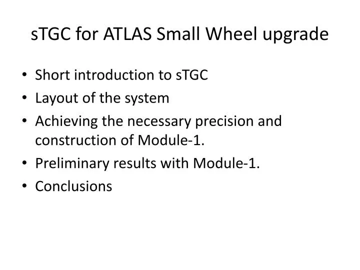
sTGC for ATLAS Small Wheel upgrade. Short introduction to sTGC Layout of the system Achieving the necessary precision and construction of Module-1. Preliminary results with Module-1. Conclusions. Aging tests (I).

E N D
sTGC for ATLAS Small Wheel upgrade • Short introduction to sTGC • Layout of the system • Achieving the necessary precision and construction of Module-1. • Preliminary results with Module-1. • Conclusions
Aging tests (I) • Many aging tests have been performed since 1997 at different flow rates, showing no deterioration of performance with rates (up to 1.3C/cm (Fukui et al, NIM A419 (1998), 497-502. • This was followed in 2007 by a long irradiation up to 6C/cm showing the same lack of effect. The n-pentane, being a good cleaning agent helps in keeping clean wires, while the quasi saturation of the operation, makes it insensitive to small wire deposits.
By going to a low resistivity cathode (100KOhm/square), one can increase the rate capabilities to <30 KHz/cm2. Both elements have been implemented in 10 small prototypes that have been tested during the last year. Most important, they need to be able to take the high radiation levels of SLHC. A small chamber has accumulated 6 Coulomb/cm, without any deterioration= 20 years at SLHC with safety factor 5. Anode and cathodes were analyzed for deposits in Chile, where a new Lab was established to continue radiation tests. Aging tests (II) Deposits due mainly to Carbon and Oxygen
Principle of the system:reduced number of channels to use for trigger by making coincidence with pads. • Make a 3-out-4 coincidence to select what strips to be readout for trigger • Fast detectors consistent with 40MHz bunch crossing. • Get PH information from the relevant strips using flash-ADC. • Reject info from any layer containing too many strips (δ-ray) or too high PH (neutron). • Angular resolution of single quadruplet (for trigger 2.9mrad), while between the 2 quadruplets in the New Small wheel, 35cm apart, this gives <0.5mrad.
Layout of the system • To reduce μ trigger rate in forward direction, need accurate vector (>1mrad) in front of magnet. • Groups from Canada, Chile, China and Israel developed the sTGC that have achieved good position (~70μm) resolution and high efficiency in high background environment • Two type of detectors to be used in ATLAS Phase I New Small Wheel (NSW) upgrade (sTGC & MicroMegas). • New method to produce large (2X1.2m²) multi-layer PCB’s had to be developed that can be placed with respect t each other with a precision of 40μm. • First final size quadruplet of such a detector has been tested at FERMILAB (T1049 in M6-FTBF between 9/5 to 20/5).
The necessary mechanical precision and alignment between strips in the 4 layers is achieved by machining the cathode boards with CNC, together with the alignment incerts • 2 different type of strips shifted by ½ strip to avoid systematics. • The 100μm pre-preg is then glued using standard PCB multi-layer technology. • This allows the construction of precise, large cathode boards. • The boards are precise in the thickness to within 30μm.
Vacuum system in granite table with jig holding precision pins
Back of the Al Honeycomb plate • Internal rubber supports only used to close individual planes, so inner chamber supports under pressure. • For gluing layers with 4.9mm honeycomb, 5.1mm glass-fiber frame, only outer frame rubber support is kept.
Leave space for glue, when gluing honeycomb, using soft plastic 100μm sheet
Flatness achieved for quadruplet, better than 50μm RMS, maximal deviation 250μm Relative alignment between strip boards consistent within 10μm across detector with the wrongly produced boards (inserts and strips not machined in one go). Prototype -1: Strip alignment
Test beam set-up • Sandwich the sTGC quadruplet prototype between 2 pixel telescopes (EUDET)
Relative shift between pairs of layers consistent with ½ strip
Relative bias of position due to final size strips, observed and corrected.
While using outside telescope not correcting for MS, gives worst resolutions, but consistent with needs
Conclusions • sTGC technology seems to be ripe for the production of the ATLAS New Small Wheel, and provides the needed performance. • Most of the manufacturing problems have been understood and corrected. • One should be able to move to the first mass production module, to be produced before the end of the year.