Download

1 / 47
510 likes | 661 Views
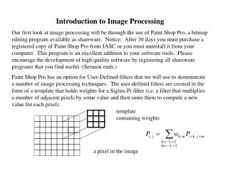
Introduction to Image Processing. Signal processing dealt with the manipulation of one-dimensional arrays corresponding to signals. Image processing deals with the manipulation of two-dimensional arrays corresponding to images.

E N D
Signal processing dealt with the manipulation of one-dimensional arrays corresponding to signals. Image processing deals with the manipulation of two-dimensional arrays corresponding toimages.
One method of signal processing dealt with the transformation of discrete-time signals into the frequency domain. An example of this transformation was the DFT:
After taking the DFT, we then performed a “filtering” process by enhancing some frequency components while attenuating other frequency components. After performing operations on the frequency components, an inverseDFT was performed to obtain the output signal.
The DFT operation could be represented by a matrix multiplication of a discrete-time sample vector: The vectors x and X are Nx1 matrices (vectors). W is an NxN matrix.
The frequency-domain vector X can then be filtered, and the filtered vector can be converted back to time-domain.
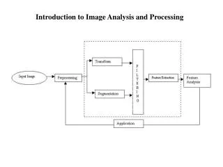
Similar processing can be performed on two-dimensional arrays. The transformation, however, is itself two-dimensional.
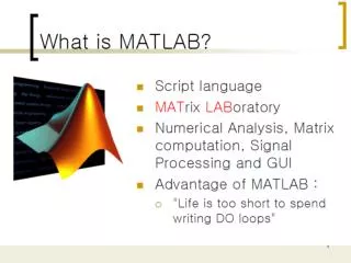
The two-dimensional transformation operates on the rows and columns of x. On the following slide is a MATLAB script demonstrating the two-dimensional discrete Fourier transformation [fft2()].
» n1 = 0:31; » n1 = n1/32; » n2 = 0:31; » n2 = n2/32; » x = kron(cos(2*pi*n1),cos(2*pi*2*n2)'); » mesh(n1,n2,x); » X = fft2(x)/1024; » mesh(0:15,0:15,abs(X(1:16,1:16))); The graphics outputs are shown on the following two slides.
The matrix transformation process can be achieved (as with signals) using matrix multiplication: The matrices x and X are N1xN2 matrices. W1 is an N1xN1 matrix; W2 is an N2xN2 matrix.
The frequency-domain matrix X can then be filtered filtered using a matrix H. The filtered matrix (Y) can then be converted back to time-domain. The filter matrix H is called a mask.
As an example of image processing, we could transform a picture with “high-frequency” components, and filter-out these high-frequency components.
» n1 = 0:31; » n1 = n1/32; » n2 = 0:31; » n2 = n2/32; » x = zeros(32,32); » for k1=1:2:11 » for k2=1:2:11 » x = x + kron(sin(2*k1*pi*n1)/k1,sin(2*k2*pi*2*n 2)'/k2); » end; » end; » mesh(n1,n2,x);
» X = fft2(x)/1024; » mesh(0:15,0:15,abs(X(1:16,1:16))); » H = zeros(32,32); » H(1:4,1:2) = ones(4,2); » H(29:32,1:2) = ones(4,2); » H(1:4,31:32) = ones(4,2); » H(29:32,31:32) = ones(4,2); » Y = H.*X; » y = real(ifft2(Y)); » mesh(0:15,0:15,abs(H(1:16,1:16))); » mesh(0:15,0:15,abs(Y(1:16,1:16))); » mesh(n1,n2,y);
In the MATLAB script, the mask matrix H was created in the following way: » H = zeros(32,32); » H(1:4,1:2) = ones(4,2); » H(29:32,1:2) = ones(4,2); » H(1:4,31:32) = ones(4,2); » H(29:32,31:32) = ones(4,2); The full mask (from k1, k2 = 0 to 31) looks like the image on the following slide.
The reason for the extra filtering blocks at the “corners” is to take into account aliasing. The corner blocks are like “frequency mirrors.” Aliasing occurs in two dimensions.
This process of masking a transformed image can be used in image compression. Suppose an image consists of mostly “low-frequency” components. We can apply a mask to the FFT of the image, and store only the non-zero components of the masked image. As an example, suppose we have an image corresponding to the two-dimensional signal in the first example: a two-dimensional sinewave with frequencies 1 Hz and 2 Hz in the first and second dimensions.
We could take the FFT, and only store the components k1=0,1 and k2=0,1,2. We can then perform a “compression” by a factor of 162/(2•3). (Here we only concentrate on the non-aliased components of the spectrum.)
The Discrete Cosine Transform An easier-to-use transform to perform compression is the discrete Cosine transform(DCT). The DCT has only real components, and the mask does not need to take into account aliases.
As with the DFT, the DCT, can be represented by a matrix multiplication of a discrete-time sample vector: The elements of W correspond to
The two-dimensionalDCT can be constructed using two matricesW1 and W2:
We can then apply a mask H to the matrix (image) X: The non-zero portion of the masked matrix (Y) can then be stored (using fewer bits or bytes than the original image x).
The stored image Y can be transformed back into an image using The restored image y generally suffers some degradation, but not as much degradation if we simply “throwing away pixels” or going to a lower resolution in order to achieve compression.
To summarize, the transformation, masking (compression), decompression process is This process is performed in .jpeg image storage.
In the examples that follow the two-dimensional DCT transformation was applied to some images with various factors of compression. The factors of compression are equal to k2, where k is the compression factor in one-dimension. Since many versions of MATLAB do not come with a two-dimensional DCT function, a MATLAB script file dct2.m is available (on my website in the zipped course file).
See also the MATLAB script file imagedemo.m (on my website in the zipped course file).