Download
1 / 11
120 likes | 304 Views
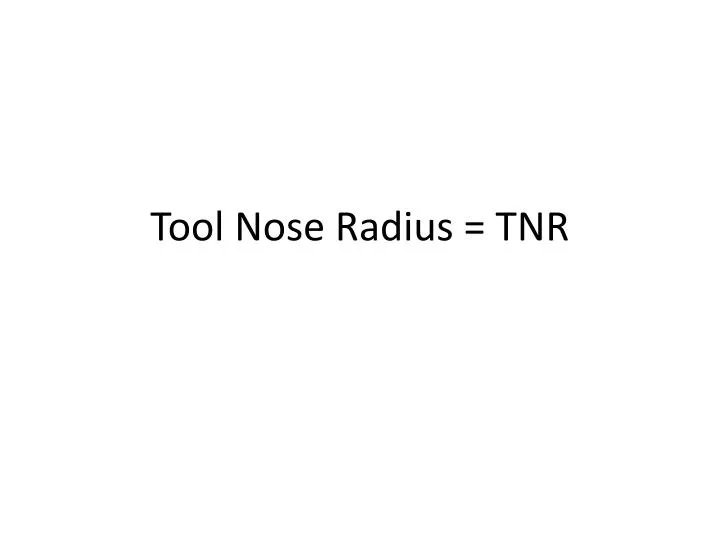
Tool Nose Radius = TNR. Tool nose radius. An offset feature used on turning center that slightly shifts the tool path for a round tip on an insert during multi-axis operation The X and Z axis of tool create a square point and most of tools for turning have radii. TNR.

E N D
Tool nose radius • An offset feature used on turning center that slightly shifts the tool path for a round tip on an insert during multi-axis operation • The X and Z axis of tool create a square point and most of tools for turning have radii
TNR • X and Z tool offsets to the tool change • Size of the TNR Standard radii are: 1/64 or .0156 1/32 or .0312 3/64 or .0469 • Tool nose vector • The tool tip of single pointed tool has specific location from the center of the TNR • The tool nose vector indicates this location to the controller(P320)
TNR compensation • G code activating TNR compensation is entered as a separate block in the program G41, G42
Circular interpolation • Direct Arc Programing line: • Direction G 03, • N010 G03 x2.00 Z -0.50 R 0.50
Circular interpolation Direct Arc Programing line: Direction G 02,