Download
1 / 8
80 likes | 221 Views
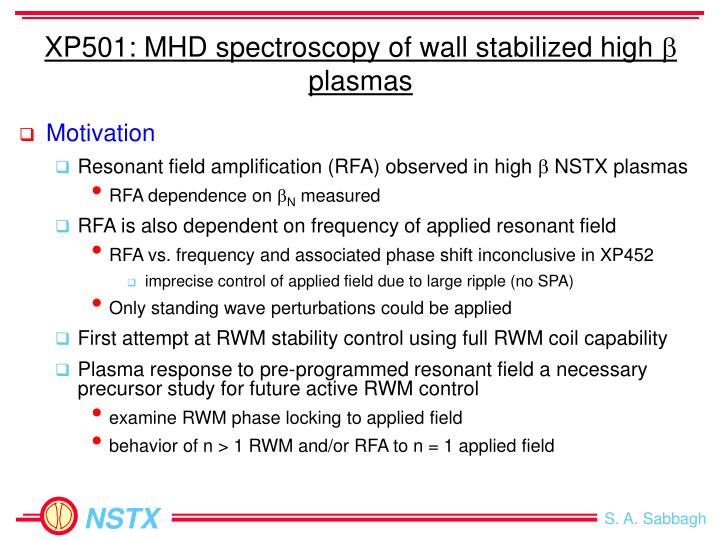
XP501: MHD spectroscopy of wall stabilized high b plasmas. Motivation Resonant field amplification (RFA) observed in high b NSTX plasmas RFA dependence on b N measured RFA is also dependent on frequency of applied resonant field

E N D
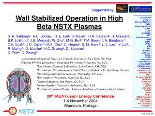
XP501: MHD spectroscopy of wall stabilized high b plasmas • Motivation • Resonant field amplification (RFA) observed in high b NSTX plasmas • RFA dependence on bN measured • RFA is also dependent on frequency of applied resonant field • RFA vs. frequency and associated phase shift inconclusive in XP452 • imprecise control of applied field due to large ripple (no SPA) • Only standing wave perturbations could be applied • First attempt at RWM stability control using full RWM coil capability • Plasma response to pre-programmed resonant field a necessary precursor study for future active RWM control • examine RWM phase locking to applied field • behavior of n > 1 RWM and/or RFA to n = 1 applied field
XP501: MHD spectroscopy of wall stabilized high b plasmas • Goals • Examine RWM physics at marginal stability • Use more precise plasma rotation control by RWM coil/SPA to control proximity to / violation of RWM critical rotation frequency • Measure RWM rotation at marginal stability; RWM growth/damping rates • Examine phase coupling of rotating RWM to applied field • Perform MHD spectroscopy on passively stabilized plasmas • Find RFA amplitude / phase response to applied field rotation frequency • Compute stable RWM growth/damping rate and mode rotation frequency • Compare measured values to single mode model fit, and theory • Determine RFA amplitude / phase shift vs. bN in longer pulse target • Look for low frequency mode resonances • by varying frequency of applied RWM coil perturbation • by varying frequency of power systems to shaping coils
Resonant Field Amplification increases at high bN NSTX DIII-D • Plasma response to applied field from initial RWM stabilization coil pair • AC and pulsed n = 1 field • RFA increase consistent with DIII-D • Stable RWM damping rate of 300s-1 measured in NSTX bNno-wall (n = 1) plasma DBp / applied Bp bN
RFA is observed to be dependent on applied field frequency • Fit to RFA amplitude / phase data yields • stable RWM damping rate • mode rotation frequency • “Single mode” empirical RWM model typically used • is this applicable for NSTX with n > 1 RWM response? • Will NSTX results be consistent with theory (e.g. Fitzpatrick-Aydemir)? H. Reimerdes, et al., EPS Meeting 2004.
Spectroscopy XP expands upon experiments in other devices • Generate relatively long pulse target with bN > bNno-wall • follows 2004 NSTX XP452 • Scan applied n=1 field frequency • utilize CY2005 RWM coil capabilities • Only requires pre programmed modulated n=1 field • Compare RFA to theory / other devices • dependence on frequency, bN • NSTX can compare measured RWM rotation frequency to fitted model and theory • Scans to examine resonances • might be more complex than “single mode” model allows MHD spectroscopy in DIII-D (H. Reimerdes et al.)
Duration and Required / Desired Diagnostics • XP could be completed in 1.0 - 1.5 run days • for n=1 applied field (additional time needed for n=2 applied field) • will provide important information for other RWM XPs • Required • Magnetics for equilibrium reconstruction • Internal RWM sensors • CHERS toroidal rotation measurement • Thomson scattering • Diamagnetic loop • Desired • USXR diagnostic at two toroidal positions • MSE • Toroidal Mirnov array
XP501: MHD spectroscopy of high beta plasmas - Run plan Task Number of Shots 1) Determine marginal stability point vs. applied DC field (toroidal rotation dropping below critical rotation frequency) A) Vary applied current, zero rotation of applied field, DC square wave pulse: (i) 2 to 3 NBI sources (step up or down), longest possible pulse with bN / bNno-wall > 1 1 (ii) Apply RWM coil current in steps until RWM is destabilized (gives Wcrit scan too) 4 (iii) 1.5 or 2 NBI sources (bN / bNno-wall < 1) in above to compare 1 2) Determine RFA dependence on applied field rotation frequency and bN A) Vary applied field rotation frequency: (Apply rotating field early (bN / bNno-wall < 1) through planned end of discharge) (i) 2 - 3 NBI sources, vary applied field frequency 0, 7, 12, 20, 30, 40, 60 Hz 7 (ii) 2 - 3 NBI sources, vary applied field frequency -7, -12, -20, -30, -40, -60 Hz 6 B) 1 NBI source at GMS frequency that produced maximum RFA amplitude 1 3) Determine RFA behavior and mode dynamics near marginal stability A) Vary applied current, applied field rotating at max. RFA from step (2) + DC offset: (Apply rotating field early (bN / bNno-wall < 1) through end of discharge) (i) Vary applied field DC offset in steps until RWM is destabilized 3 (ii) Finer applied field frequency scan (3 more points) 3 B) Decrease RWM coil current to below marginal stability, vary PF MG set frequency 4 4) Vacuum field shots for each frequency used (if necessary) 3 5) (Optional) repeat the most successful trials above with n = 2 applied field (optional 20) Total: 33
Schematic Waveforms for GMS coil – XP501 • Schematic waveforms based on XP452 x103 6 X10 5 GMS coil current 1.0 Plasma current 1 2 (varybN, constant pulse) 0 Amps 0.5 (vary frequency, constant bN) 3 -5 0 0 0.1 0.2 0.3 0.4 0.5 0.6 0.7 6 Default NBI timing Bt = 3kG plan Source C – timing varies with Ip 4 (arb) Source A 2 Source B 0 0 0.1 0.2 0.3 0.4 0.5 0.6 0.7 Time (Seconds)