Download
1 / 14
140 likes | 240 Views
1 System 2 Interface 3 Address Translation 4 IP 5 ICMP. 6 TCP 7 UDP 8 EGB (9 CMOT) 10 Transmission 11 SNMP . MIB-II RFC 1213. Systems Group .1.3.6.1.2.1.1. 1 sysDescr 2 sysObject ID 3 sysUpTime 4 sysContact 5 sysName 6 sysLocation 7 sysServices. ifNumber ifIndex

E N D
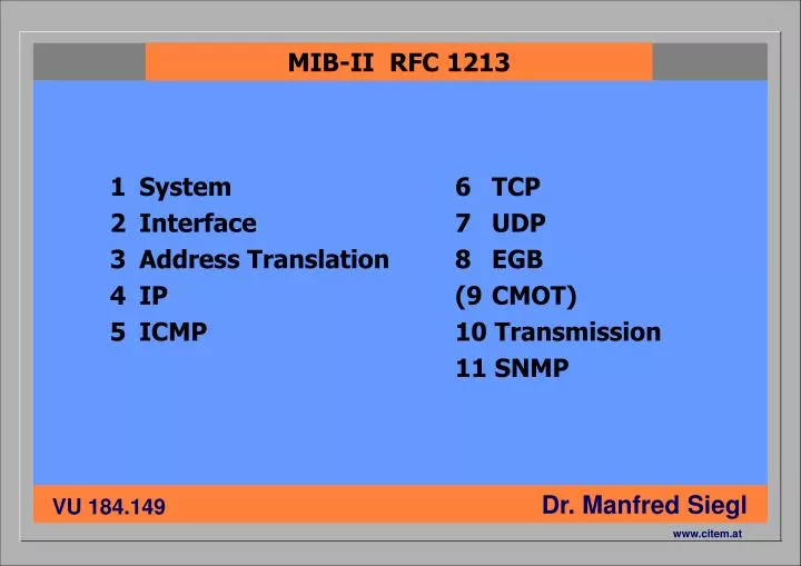
1 System 2 Interface 3 Address Translation 4 IP 5 ICMP 6 TCP 7 UDP 8 EGB (9 CMOT) 10 Transmission 11 SNMP MIB-II RFC 1213
Systems Group .1.3.6.1.2.1.1 1 sysDescr 2 sysObject ID 3 sysUpTime 4 sysContact 5 sysName 6 sysLocation 7 sysServices
ifNumber ifIndex ifDescr ifType ifMtu ifSpeed ifPhysAddress ifAdminStatus ifOperStatus ifLastChange IfInOctets ifInUcastPkts ifinNUcastPkts ifInDiscards ifInErrors ifInUnknownProtos Interface Group .1.3.6.1.2.1.2 • ifOutOctets • ifOutUcastPkts • ifOutNucastPkts • ifOutDiscards • ifOutErrors • ifOutQLen
RMON - Remote Monitoring Beobachtung der Ressourcen durch eine RMON-Probe an einer entfernten Stelle im Netz und Übermittlung der Ergebnisse über SNMP • Ethernet statistics • history control • ethernet history • alarm • host • hostTopN • matrix • filter • packet capture • event
RMON2 - Remote Monitoring 2 • protocol directory • protocol distribution • address mapping • network layer host • network layer matrix • application layer host • application layer matrix • user history • probe configuration
ISO/OSI Layer Model Anwendungsschicht 7 Gateway 7 Darstellungsschicht 6 6 Kom.steuerungsschicht 5 5 Transportschicht 4 4 Vermittlungsschicht 3 Router 3 Sicherungsschicht 2 Bridge/Switch 2 Bit-Übertragungsschicht 1 Repeater/Hub 1
Paketaufbau TCP / IP / Ethernet UDP/TCP Header Layer 3 Router Layer 2 Switch Bridge Layer 1 Repeater Hub Port IP Header Dest Src Eth Header CRC Dest Src Eth Präambel
MAC Adresse IP-Adresse Internet-Name 00 : 00 : 21 : 6B : 93 : AC 128 . 130 . 2 . 9 www . tuwien . ac . at Kennzeichnung eines Knotens
Class A Class B Class C 0_______.________.________.________ 11111111.00000000.00000000.00000000 255.0.0.0 10______.________.________.________ 11111111.11111111.00000000.00000000 255.255.0.0 11______.________.________.________ 11111111.11111111.11111111.00000000 255.255.255.0 IP ADDRESS CLASSES
Struktur gemäß EN50173 ASG: Anwenderspezifische Geräte SV: Standortverteiler GV: Gebäudeverteiler EV: Etagenverteiler KV: Kabelverteiler TA: Endknotenanschlüsse SV ASG GV GV ASG ASG EV ASG ASG ASG ASG KV KV TA TA TA TA
Kriterien für einen IT-Verteilerraum 19-Zoll Schränke (80x80x220cm³) vorne 1m20, hinten 80cm • Platzbedarf 1000 bis 1500 Watt Abwärme je 19-Zoll Schrank • Wärmeentwicklung Kühlventilatoren mit hoher Lärm-entwicklung - für Arbeitsplatz-räume nicht geeignet • Lärmentwicklung Unautorisierten Zugang verhindern • Zugänglichkeit separate FI/LS (2 je Schrank), USV, Überspannungsableiter • Stromversorgung Fernsignalisierung der Zustände, Wartungspersonal vor Ort • Management
Kriterien für die Kabelauswahl • Kabeldurchmesser (6mm bis 20mm) • minimale zulässiger Biegeradius (5cm bis 35cm) • maximale Zugkraft (150N bis 3000N) • maximale verlegbare Länge (90m bis 2km oder mehr) • Dimensionierung und Ausführung der Tragsysteme • Fehleranfälligkeit im Benutzerbetrieb • einsetzbare Technologien • Eigenschaften im Brandfall (Brennbarkeit, rauchhemmend, säurebildend)
Shielded Twisted Pair - STP 4 einzeln verdrillte Adernpaare, jedes Paar mit leitender Folie geschirmt, gemeinsam verseilt, im gemeinsamen Kabelmantel,optional mit gemeinsamen Geflechtschirm STP-C 2x 2STP-C
Unshielded Twisted Pair - UTP 4 einzeln verdrillte Adernpaare,gemeinsam verseilt, im gemeinsamen Kabelmantel,optional mit gemeinsamen Folienschirm UTP S-UTP