Download
1 / 37
370 likes | 503 Views
Silicon Strip R&D Activity in Korea. B.G. Cheon (Chonnam Nat’l Univ.) On behalf of Korean Silicon Working Group. Introduction Sensor design and simulation Pre-results of 1 st mask performance Status of 2 nd mask design Summary. Korean silicon working group.

E N D
Silicon Strip R&D Activity in Korea B.G. Cheon (Chonnam Nat’l Univ.) On behalf of Korean Silicon Working Group Introduction Sensor design and simulation Pre-results of 1st mask performance Status of 2nd mask design Summary
Korean silicon working group • Generic silicon sensor R&D since 2001 • Silicon charge detector for CREAM balloon experiment • Started working on silicon sensor R&D for Belle upgrade • Looking for any application to other fields • 7 institutions so far … Kyungpook National University Ewha Women’s University Seoul National University Korea University Yonsei University Sungkyunkwan University Chonnam National University
Silicon tracker R&D for ILC • Global design layout/parameter concepts can be referred to other presentations in this workshop. • Intermediate tracker - tracking efficiency - linking efficiency - matching efficiency - standalone tracker • main tracker - momentum resolution - tracking efficiency
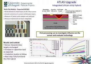
DSSD sensor design n+ ohmic side 1st metal p+ junction side 2nd metal readout line Metal 1 and metal 2 contact (VIA) n+ ohmic components: # : implanted n+ # : p-stop # : SiO2 # : Al for readout p+ junction components: # : implanted p+ # : 1st metal # : SiO2 # : VIA # : 2nd metal • Double-sided silicon strip sensor type • Three metal process • Implanted strips in ohmic side are orthogonal to the strips in juction side • Readout strips in junction side are parallel to the strips of ohmic side
DSSD sensor simulation • Simulation package : Silvaco TCAD • ATHENA – process simulation • ATLAS – device simulation • PIN diode simulation calibrates DSSD simulation • Structure & mesh • Implantation (Boron, Phosphorus) • Electric potential & field • IV & CV characteristics • Response of injected photon into the DSSD
Structure N-type Si(100), 8.5kW, 380mm
Implantation N strip = Phosphorus P stop = Boron P strip = Boron Annealing 900oC, N2, 90min at P+ Annealing 900oC, N2, 140min at N+
IV & CV Leakage current (I-V) C-V 1/C2 -V
Photon injection into DSSD photon : wavelength = 0.6mm, intensity=100W/cm2 0V -150V Total current density e- current density h+ current density
Wafer layout (1st mask) Mask design package : Cadence (Solaris)
Sensor profiles p+ implanted readout strip n+ implanted p-stop in atoll readout pad in staggering VIA in hourglass guard ring n+ side p+ side
P-side measurement Probe n bulk pad(ground) on n-side & p-guard ring (-) on p-side
Total leakage current/sensor These are disappeared after insulating wafer edges
Specification of 2nd mask design Multi-purpose mask: sensors + various test patterns
N-side 512ch 50mm pitch 64ch 50mm pitch 1x1cm2 PIN diode 32ch 50mm pitch 16ch 50mmpitch For SDD R&D Pixel Array Rear-side of SSD
P-side 512ch 100mm pitch w/o hourglass (sensor-1) 64ch 100mm pitch 1cm PIN diode 32ch 100mm pitch For SDD R&D 16ch 100mm pitch Pixel array 512ch 100mm pitch w/ hourglass (sensor-2) 16ch 100mm pitch SSD
P-side (sensor-1) Implant w/ hourglass 512ch 100mm pitch sensor • perpendicular to metal • designed to reduce capacitance • not applied to VIA region
Test pattern: Miniature • S/N measurement of each pitch strip sensor after making wire bonding complete. • Three types of sensors have been prepared. • - 16/32/64 channels P-side :16ch 100mm pitch Sensor Case of wire bonding N-side :16ch 50mm pitch sensor
Test pattern: P-side SSD SiO2 contact 1st Metal • P-side: two metal processes • It is needed to make it compatible with other p+ implantation. p+ VIA SiO2 2nd Metal 16ch 100mm pitch sensor(55610 x 5560) Metal Metal size is larger than p+ implant by reducing contact size. p+ implantation Metal size is smaller than p+ implant by keeping contact size. Metal p+ implantation
Test pattern: pixel array • Pixel size : 25☓25, 50☓50, 100☓100 (mm2) • Each sensor array : 5☓5 matrix • Readout pad option was added to make wire bonding easy during the measurement of S/N Case of wire bonding in each diode Case of readout pad in each diode
Test pattern: SDD 50mm☓50mm n+ implant 100mm☓100mm metal • R&D pattern for Silicon Drift Detector • Sensor size : 1cm ☓ 1cm (guard ring included) • N-side : n+(sensor) & p+ implant except the sensor • P-side : p+ implant in total
Summary • DSSD sensors fab-out (~20 wafers, 3 sensors/wafer) and IV & CV have been measured. • automatic probe station & wirebonder purchased and installed • faster and more reliable measurement • 2nd mask design including various test patterns is almost ready. • Fabrication and measurement will be done within two months. • Silicon Drift Detector R&D has just been started. • Irradiation test for checking sensor rad-hardness is being planned. • Readout & DAQ design and production are in progress.
CREAM Silicon Charge Detector • CREAM(Cosmic Ray Energetics And Mass) balloon exp. • To measure energy spectrum of each elements in 1012 ~1015 eV • First mission of design, fab. and integration performed in Korea • Sensor size=1.1cm2 ; S/N>4 ; Total 1000 channels
Electric potential Reverse bias ( 0V ~ -90V )
Electric field P_strip region(P+) N wafer region P_strip’s doping concentration is higher than N wafer’s. So N_bulk region’s electric field is spread out widely, but the slope of P_strip region’s field is very steep. In depletion region, electric field is not zero.
Electron concentration The higher reverse bias is, the larger depletion region is
Recombination rate The higher reverse bias is, the larger depletion region is
N-side sensor p-stop guard ring pad 512ch 50mm pitch sensor
P-side (sensor-2) Implant w/o hourglass 512ch 100mm pitch sensor • hard to implementhourglass in the mask process • compare btw w/ and w/o hourglass
Test pattern: SDD type-1 • Silicon Drift Detector R&D를 위한 pattern • guard ring을 포함한 크기 : 1cm ☓ 1cm • N-side에 센서를 두고 뒷면은 무공정 • 센서의 배열에 따라 세 종류가 있다. 50mm☓50mm n+ implant 100mm☓100mm metal
Implantation N strip = Phosphorus P strip = Boron P stop = Boron Annealing 900oC, N2, 90min at P+ Annealing 900oC, N2, 140min at N+