Download
1 / 22
230 likes | 348 Views
INITIAL STUDIES on PROTON COMPUTED TOMOGRAPHY USING SILICON STRIP DETECTORS L. Johnson, B. Keeney, G. Ross, H. F.-W. Sadrozinski, A. Seiden, D.C. Williams, L. Zhang Santa Cruz Institute for Particle Physics, UC Santa Cruz, CA 95064 V. Bashkirov, R. W. M. Schulte, K. Shahnazi

E N D
INITIAL STUDIES on PROTON COMPUTED TOMOGRAPHY USING SILICON STRIP DETECTORS L. Johnson, B. Keeney, G. Ross, H. F.-W. Sadrozinski, A. Seiden, D.C. Williams, L. Zhang Santa Cruz Institute for Particle Physics, UC Santa Cruz, CA 95064 V. Bashkirov, R. W. M. Schulte, K. Shahnazi Loma Linda University Medical Center, Loma Linda, CA 92354 • Proton Tomography / Proton Transmission Radiography • Proton Transmission Radiography Data • Proton Transmission Radiography MC Study
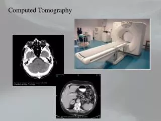
Computed Tomography (CT) • Based on X-ray absorption • Faithful reconstruction of patient’s anatomy • Stacked 2D maps of linear X-ray attenuation • Coupled linear equations • Invert Matrices and find (hopefully) non-malignant structures X-ray tube Detector array
Radiography: X-rays vs. Protons Energy Loss of Protons, r Attenuation of Photons, z N(x) = Noe- m x NIST Data
Proton Radiography: Density Map NIST Data
Development of Proton Beam Computed Tomography • Exploratory Study in Proton Radiography • two detector planes • Crude phantom in front • Experimental Study • two detector planes • water phantom on turntable • Theoretical Study • GEANT4 MC simulation • influence of MCS and range straggling • importance of angular measurements • Optimization of energy
Proton Energy Measurement with LET Simple 2D Silicon Strip Detector Telescope built for Nanodosimetry (based on GLAST Design) 2 single-sided SSD 194um Pitch 400um thick 1.3us shaping time Binary readout Time-over-Threshold TOT Large dynamic range Measure particle energy via LET
GLAST Front-End Electronics ASIC • Binary Readout: • Low-power (~200uW/channel) • Peaking time ˜ 1.3 ms • Low noise (Noise occupancy <10-5) • Threshold set in every ASIC • Separate Masks for Trigger and Readout in every Channel • Self - Trigger = OR of one Si plane (1536 channels) Electron Events Pulse Charge: Time – over-Threshold on the OR of every Si plane Distinguish single tracks from two tracks in one strip Photon Events
Charge ~ Time-Over-Threshold (TOT):Digitization of Position and Energy with large Dynamic Range Time-over-Threshold TOT Pulse Threshold TOT charge LET!
Proton Energy Measurement with LET TOT Spectra as for several proton energies Mean TOT vs. Proton Energy Good agreement between measurement and MC simulations
Proton Energy Measurement with LET TOT Resolution “~flat”. Energy Measurement possible where slope dTOT/dE is large TOT Spectra vs. energy
1 2 - SSD modules Air Air Wax block Object Beam from Synchrotron 30 cm 27.3 cm 1 2 4 3 - SSD detector planes y x x y 130MeV 60+130MeV 250MeV Exploratory Proton Radiography Set-up Use Loma Linda University Medical Ctr 250 MeV Proton Beam Degraded down to 130 MeV by Wax Block Object is Aluminum pipe 5cm long, 3cm OD, 0.67cm ID Very large effects expected, but beam quite non-uniform
Image ! • Subdivide SSD area into pixels • Strip x strip 194um x 194um • 4 x 4 strips (0.8mm x 0.8mm) • Image given by average • TOT or Energy in pixel
Issues Features: Washed out image in 2nd plane Fuzzy edges Hole filled partially Energy diluted at edges and in hole Migration of events All explained by Multiple Coulomb Scattering
Migration and Energy Dilution in Slice Data shows increased frequency of hits in boundary of the pipe: the hole and the outside perimeter. These events are associated with a dilution of the energy profile Hit frequency vs. Location Mean Energy vs. Location Energy lowered Excess Events Blurred Edges Approx. Beam Profile
Multiple Scattering: Emigration Protons scatter OUT OF Target (not INTO). Those have larger energy loss larger angles fill hole dilute energy
Energy Resolution = Position Resolution Data (LET converted to Energy) GEANT4 MC (LET in SSD) RMS Simulation reproduces spread of energy and loss of resolution
Energy Resolution Object Background Data: LET converted to Energy MC: LET in SSD plane
Migration: MC Dilution by events entering the Object but leaving it before the end
MC: Loss of Resolution in Back First Plane, 2cm behind Object Second Plane, 30cm behind Object
Conclusions • Imaging with protons is working! • GEANT4 program describes the data well • (energy and position resolution, migration) • Issues: • Energy needs Optimization depending on Target • Improve resolution with cut on exit angle? • Investigate independent Energy measurement • Dose – Contrast - Resolution Relationship to be explored • Next steps: pCT